MIL- STD-883F 2004 TEST METHOD STANDARD MICROCIRCUITS.pdf - 第348页
MIL-STD-883F METHOD 2018.4 18 June 2004 36 APPENDIX A Metal int egrit y alter nate to SEM ins pecti on 10. PURPOSE . Metal integri ty is achieved t hrough a s ystem of designi ng and building i n qualit y and reli ab ili…
MIL-STD-883F
METHOD 2018.4
18 June 2004
35
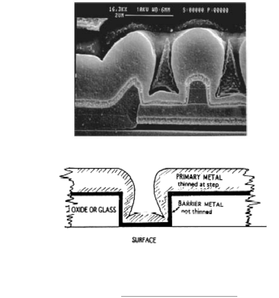
Figure 2018.24 20% metallization coverage (barrier metal inclusive)
*
*
*
*

MIL-STD-883F
METHOD 2018.4
18 June 2004
36
APPENDIX A
Metal integrity alternate to SEM inspection
10. PURPOSE
. Metal integrity is achieved through a system of designing and building in quality and reliability. It is not
practical or cost effective to rely solely on end-of-line testing to ensure metal integrity. This procedure provides a system for
designing, building, and monitoring a metal system that withstands the operating conditions of the device for the specified
lifetime.
20. SCOPE
20.1 Utilization of this method provides an alternate to the requirements defined in TM2018. This procedure must be
used in conjunction with the requirements of alternate 2 of TM5004, paragraph 3.3.1 as it applies to metallization.
20.2 This procedure describes a method by which metal integrity is assured through a combination of design rules and
techniques, process development, manufacturing controls and end-of-line screening and reliability testing.
20.2.1 Design controls
.
a. Reliability rules.
b. Layout rules.
c. Rules checking.
d. Process development.
20.2.2 Manufacturing controls
. Statistical control of the manufacturing process and equipment defect and foreign
material control.
20.2.3 Reliability testing
. Accelerated tests.
30. DEFINITIONS
Lifetime
. The mean time to failure of a technology at operating conditions defined to be normal. The mean time to
failure is measured on a large sample of devices stressed at temperatures and current densities well above the normal
operating conditions and extrapolated to normal operating temperature and current density.
Current density
. The maximum allowable current density calculated as described in appendix A of MIL-PRF-38535.
Specification limits
. Minimum or maximum boundaries for the value of a measured parameter. Material whose
measured values are beyond these boundaries must be reviewed and dispositioned.
Worst case operating conditions
. Conditions of current and temperature at which a device would normally
operate, that would result in the greatest likelihood of failure.

MIL-STD-883F
METHOD 2018.4
18 June 2004
37
APPENDIX A
40. REQUIREMENTS
40.1 Design controls
. Design includes device design and process development. Device design includes all steps and
supporting systems needed to translate a functional description for a device into a pattern generating data base. Process
development includes selection of materials, tooling, and process conditions that may significantly affect metal integrity. The
design process is a major consideration in establishing metal integrity.
40.1.1 A manufacturer's design system must include controlled, documented rules based on the manufacturer's
processing capabilities. These rules shall specify feature size and spacing requirements, taking into account size changes
that occur during processing. Manufacturers shall be able to justify their rules based on expected process variations. In
addition, documented reliability rules shall exist which establish the electrical characteristics for each technology, taking into
account processing materials, tolerances and limitations. The manufacturer shall have a system for checking designs for
rule violations, and a system for correcting violations. Design rules shall consider the maximum current density (calculated
as described in appendix A of MIL-PRF-38535) which shall be determined using worst case operating conditions and taking
into consideration current crowding at contacts and vias. The manufacturer shall ensure that worst case processing
conditions (such as alignment, metal thickness, line width, and contact/via size) do not result in violation of current density.
Current density for a technology shall be at a level such that there is sufficient margin to ensure that failure will not result
from electromigration in the specified lifetime of the device.
40.1.2 Process development
. The manufacturer's design must take into consideration known levels of defects in the
process. The process developed by the manufacturer must produce metallization that has the electrical and mechanical
properties consistent with the design rules of 40.1.1, and reliability goals for the technology. Mechanical stress in the metal
after final processing shall be understood. The manufacturer shall demonstrate, with results from appropriate designed
experiments, that the desired electrical and mechanical properties have been achieved, and that the interaction of other
process parameters on metal integrity parameters (minimum list in 40.2) is understood. The initial process specification
limits shall be chosen such that metal integrity parameters are within the capability of the process. The manufacturer shall
have a change control system in place such that new or changed processes are not put into production without the
appropriate reliability evaluation.
40.2 Manufacturing controls
. The manufacturer shall establish manufacturing controls in order to achieve uniformly good
quality and reliability in their metal system, and to assure that the product is being manufactured according to the
assumptions made during design. The manufacturer shall determine which parameters are critical to metal integrity and
control those parameters in accordance with EIA 557. The manufacturer shall be able to demonstrate control of metal
thicknesses, step coverage and cross-sectional areas, metal line width, contact and via sizes, contact and via resistance,
and sheet resistance as a minimum, and show that they are being controlled to limits that are consistent with the way the
metal system was designed. Specification limits shall be established for these parameters. In addition, defects that
threaten metal integrity must be controlled in accordance with the alternate visual procedure (alternate 2) in appendix A of
TM5004.
40.3 Reliability testing
. While it is desirable to design in and build in reliability rather than to achieve reliability by
screening finished product, there is valuable information to be gained from screening and reliability testing. Screening test
such as burn-in not only eliminate the weaker parts in a population, but also provide information on failure mechanisms
which can be used to improve design, materials, processes, or electrical test. Similarly, accelerated testing is used to
speed up failure mechanisms likely to occur under normal operating conditions of a device. These failure mechanisms can
then be analyzed to provide a basis for improvement. Accelerated test that a manufacturer may use to this end include but
are not limited to electromigration testing, life testing, temperature-humidity-bias testing, and temperature cycling.
Structures used in accelerated test must be typical of the technology represented. Failure mechanisms experienced during
accelerated testing must be typical of those experienced during normal use of the device.