MIL- STD-883F 2004 TEST METHOD STANDARD MICROCIRCUITS.pdf - 第35页
MIL-STD-883F METHOD 1005.8 1 June 1993 1 METHOD 1005.8 STEADY-STATE LIFE 1. PURPOSE . The st eady-st ate li fe tes t is perfor med for t he purpose of demonstr ating t he qualit y or rel iabili ty of devi ces subject ed …
MIL-STD-883F
METHOD 1004.7
17 August 1987
4
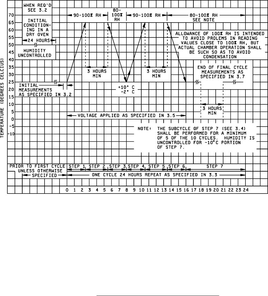
FIGURE 1004-1. Graphical representation of moisture-resistance test
.

MIL-STD-883F
METHOD 1005.8
1 June 1993
1
METHOD 1005.8
STEADY-STATE LIFE
1. PURPOSE
. The steady-state life test is performed for the purpose of demonstrating the quality or reliability of devices
subjected to the specified conditions over an extended time period. Life tests conducted within rated operating conditions
should be conducted for a sufficiently long test period to assure that results are not characteristic of early failures or "infant
mortality," and periodic observations of results should be made prior to the end of the life test to provide an indication of any
significant variation of failure rate with time. Valid results at shorter intervals or at lower stresses require accelerated test
conditions or a sufficiently large sample size to provide a reasonable probability of detection of failures in the sample
corresponding to the distribution of potential failures in the lot(s) from which the sample was drawn. The test conditions
provided in 3 below are intended to reflect these considerations.
When this test is employed for the purpose of assessing the general capability of a device or for device qualification tests in
support of future device applications requiring high reliability, the test conditions should be selected so as to represent the
maximum operating or testing (see test condition F) ratings of the device in terms of electrical input(s), load and bias and the
corresponding maximum operating or testing temperature or other specified environment.
2. APPARATUS
. Suitable sockets or other mounting means shall be provided to make firm electrical contact to the
terminals of devices under test in the specified circuit configuration. Except as authorized by the acquiring or qualifying
activity, the mounting means shall be so designated that they will not remove internally-dissipated heat from the device by
conduction, other than that removed through the device terminals, the necessary electrical contacts and the gas or liquid
chamber medium. The apparatus shall provide for maintaining the specified biases at the terminals of the device under test
and, when specified, monitoring of the input excitation or output response. Power supplies and current-setting resistors shall
be capable of maintaining the specified operating conditions as minimal throughout the testing period, despite normal
variations in source voltages, ambient temperatures, etc. When test conditions result in significant power dissipation, the
test apparatus shall be arranged so as to result in the approximate average power dissipation for each device whether
devices are tested individually or in a group. The test circuits need not compensate for normal variations in individual device
characteristics, but shall be so arranged that the existence of failed or abnormal (i.e., open, short, etc.) devices in a group
does not negate the effect of the test for other devices in the group.
3. PROCEDURE
. The microelectronic devices shall be subjected to the specified test condition (see 3.5) for the
specified duration at the specified test temperature, and the required measurements shall be made at the specified
intermediate points and end points. QML manufactures who are certified and qualified to MIL-PRF-38535 may modify the
time or the condition independently from the regression conditions contained in table I or the test condition/circuit specified
in the device specification or standard microcircuit drawing provided the modification is contained in the manufacturer's QM
plan and the "Q" certification identifier is marked on the devices. Lead-, stud-, or case-mounted devices shall be mounted
by the leads, stud, or case in their normal mounting configuration, and the point of connection shall be maintained at a
temperature not less than the specified ambient temperature. The test condition, duration, sample size, and temperature
selected prior to test shall be recorded and shall govern for the entire test. Test boards shall not employ load resistors
which are common to more than one device, or to more than one output pin on the same device.
3.1 Test duration
.
3.1.1 Test duration - standard life
. The life test duration shall be 1,000 hours minimum at 125°C , unless otherwise
specified or allowed (see 3.2.1). After the specified duration of the test, the device shall be removed from the test conditions
and allowed to reach standard test conditions. Where the purpose of this test is to demonstrate compliance with a specified
lambda (8), the test may be terminated at the specified duration or at the point of rejection if this occurs prior to the specified
test duration.

MIL-STD-883F
METHOD 1005.8
1 June 1993
2
3.1.2 Accelerated life test duration
. For class level B, the life test duration, when accelerated, shall be the time equivalent
to 1,000 hours at 125°C for the ambient temperature selected or specified (see table I). Within 72 hours after the specified
duration of the test, the device shall be removed from the specified test conditions and allowed to reach standard test
conditions without removal of bias. The interruption of bias for up to one minute for the purpose of moving the devices to
cool-down positions separate from the chamber within which life testing was performed shall not be considered removal of
bias.
3.2 Test temperature
. The specified test temperature is the minimum ambient temperature to which all devices in the
working area of the chamber shall be exposed. This shall be assured by making whatever adjustments are necessary in the
chamber profile, loading, location of control or monitoring instruments, and the flow of air or other suitable gas or liquid
chamber medium. Therefore, calibration shall be accomplished in the chamber in a fully loaded, (boards need not be loaded
with devices) unpowered configuration, and the indicator sensor located at, or adjusted to reflect, the coldest point in the
working area.
3.2.1 Test temperature - standard life
. Unless otherwise specified, the ambient life test temperature shall be 125°C
minimum for test conditions A through E (see 3.5), except that for hybrid microcircuits, the conditions may be modified in
accordance with table I. At the supplier's option, the ambient temperature for conditions A through E may be increased and
the test duration reduced in accordance with table I using the specified test circuit and bias conditions. Since case and
junction temperature will, under normal circumstances, be significantly higher than ambient temperature, the circuit should
be so structured that maximum rated case or junction temperatures for test or operation shall not exceed 200°C for class
level B or 175°C for class level S (see 3.2.1.1).
3.2.1.1 Test temperature for high power devices
. Regardless of power level, devices shall be able to be burned in or
life-tested at their maximum rated operating temperature. For devices whose maximum operating temperature is stated in
terms of ambient temperature, T
A
, table I applies. For devices whose maximum operating temperature is stated in terms of
case temperature, T
C
, and where the ambient temperature would cause T
J
to exceed +200°C (+175°C for class level S),
the ambient operating temperature may be reduced during burn-in and life test from +125°C to a value that will demonstrate
a T
J
between +175°C and +200°C and T
C
equal to or greater than +125°C without changing the test duration. Data
supporting this reduction shall be available to the acquiring and qualifying activities upon request.
3.2.1.2 Test temperature for hybrid devices
. The ambient or case life test temperature shall be as specified in table I,
except case temperature life test shall be performed, as a minimum, at the maximum operating case temperature (T
C
)
specified for the device. Life test shall be for 1,000 hours minimum for class level S hybrid (class K). The device should be
life tested at the maximum specified operating temperature, voltage, and loading conditions as specified in the detail
specification. Since case and junction temperature will, under normal circumstances, be significantly higher than ambient
temperature, the circuit should be so structured that the maximum rated junction temperature as specified in the device
specification or drawing and the cure temperature of polymeric materials as specified in the baseline documentation shall
not be exceeded. If no maximum junction temperature is specified, a maximum of 175°C is assumed. Accelerated life test
(condition F) shall not be permitted. The specified test temperature shall be the minimum actual ambient or case
temperature that must be maintained for all devices in the chamber. This shall be assured by making whatever adjustments
are necessary in the chamber profile, loading, location of control or monitoring instruments and the flow of air or other
suitable gas or liquid chamber medium.
3.2.2 Test temperature - accelerated life
. When condition F is specified or is utilized as an option (when allowed by the
applicable acquisition documents), the minimum ambient test temperature shall be +175°C , unless otherwise specified.
Since accelerated testing will normally be performed at temperatures higher than the maximum rated operating junction
temperature of the device(s) tested, care shall be taken to ensure that the device(s) does not go into thermal runaway.
3.2.3 Special considerations for devices with internal thermal limitation using test conditions A through E
. For devices
with internal thermal shutdown, extended exposure at a temperature in excess of the shut-down temperature will not provide
a realistic indicator of long-term operating reliability. For devices equipped with thermal shutdown, operating life test shall be
performed at an ambient temperature where the worst case junction temperature is at least 5°C below the worst case
thermal shutdown threshold. Data supporting the defined thermal shutdown threshold shall be available to the preparing or
acquiring activity upon request.