MIL- STD-883F 2004 TEST METHOD STANDARD MICROCIRCUITS.pdf - 第352页
MIL-STD-883F METHOD 2019.7 07 March 2003 2 3.2 F ailure criteria . A devic e which f ails any of the f ollowing c rit eria s hall c onsti tute a f ailure. Note: (S ee examples for det ermining DI E AREA foll owing figur …

MIL-STD-883F
METHOD 2019.7
07 March 2003
1
METHOD 2019.7
DIE SHEAR STRENGTH
1. PURPOSE
. The purpose of this test is to determine the integrity of materials and procedures used to attach
semiconductor die or surface mounted passive elements to package headers or other substrates. This determination is
based on a measure of force applied to the die, the type of failure resulting from this application of force (if failure occurs)
and the visual appearance of the residual die attach media and substrate/header metallization.
2. APPARATUS
. The test equipment shall consist of a load-applying instrument with an accuracy of ±5 percent of full
scale or 50 grams, whichever is the greater tolerance. A circular dynamometer with a lever arm or a linear motion force-
applying instrument may be used to apply the force required for testing. The test equipment shall have the following
capabilities:
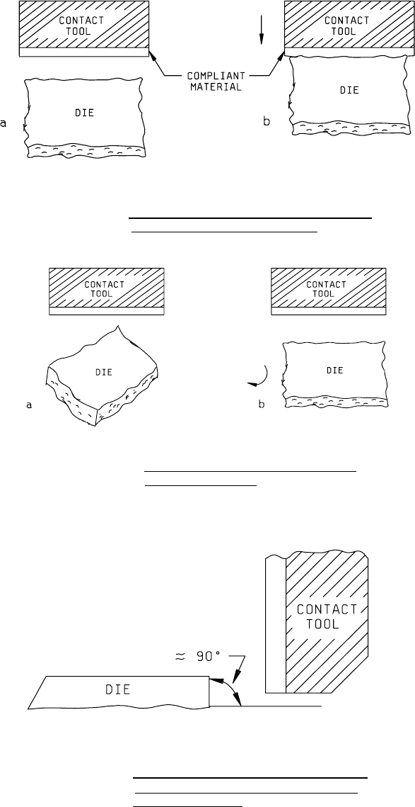
a. A die contact tool which applies a uniform distribution of the force to an edge of the die (see figure 2019-1). A
compliant (conforming) material (e.g., nail polish, tape, etc.) may be applied to th face of the contact tool to ensue
uniform force distribution on the edge of the die.
b. Provisions to assure that the die contact tool is perpendicular to the die mounting plane of the header or substrate.
c. A rotational capability, relative to the header/substrate holding fixture and the die contact tool, to facilitate line
contact on the edge of the die; i.e., the tool applying the force to the die shall contact the die edge from end-to-end
(see figure 2019-2).
d. A binocular microscope with magnification capabilities of 10X minimum and lighting which facilitates visual
observation of the die and die contact tool interface during testing.
3. PROCEDURE
. The test shall be conducted, as defined herein, or to the test conditions specified in the applicable
specific acquisition document consistent with the particular part construction. All die strength tests shall be counted and the
specific sampling, acceptance, and added sample provisions shall be observed, as applicable.
3.1 Shear strength
. A force sufficient to shear the die from its mounting or equal to twice the minimum specified shear
strength (figure 2019-4), whichever occurs first, shall be applied to the die using the apparatus of 2 above.
NOTE: For passive elements only attached at the end terminations, the area used to determine the force applied shall be
the total area of the mounting surface of the end terminations. An area between and terminations filled with non-adhering
filler shall not be used to determine the force applied. However, any adhering material applied between the end terminations
shall be used in the shear calculation, If the area between end terminations contains an adhering material, then the area of
the adhering material shall be added to the area of the mounting surfaces of the end terminations and that total area shall be
used to determine the force applied.
a. When a linear motion force-applying instrument is used, the direction of the applied force shall be parallel with the
plane of the header or substrate and perpendicular to the die being tested.
b. When a circular dynamometer with a lever arm is employed to apply the force required for testing, it shall be
pivoted about the lever arm axis and the motion shall be parallel with the plane of the header or substrate and
perpendicular to the edge of the die being tested. The contact tooling attached to the lever arm shall be at a proper
distance to assure an accurate value of applied force.
c. The die contact tool shall apply a force gradually from zero to a specified value against an edge of the die which
most closely approximates a 90° angle with the base of the header or substrate to which it is bonded (see figure
2019-3). For rectangular die, the force shall be applied perpendicular to the longer side of the die. When
constrained by package configurations, any available side of the die may be tested if the above options are not
available.
d. After initial contact with the die edge and during the application of force, the relative position of the contact tool
shall not move vertically such that contact is made with the header/substrate or die attach media. If the tool rides
over the die, a new die may be substituted or the die may be repositioned, provided that the requirements of 3.1.c
are met.

MIL-STD-883F
METHOD 2019.7
07 March 2003
2
3.2 Failure criteria. A device which fails any of the following criteria shall constitute a failure.
Note: (See examples for determining DIE AREA following figure 2019-4.)
a. Fails die strength requirements (1.0X) of figure 2019-4.
b. Separation with less than 1.25 times the minimum strength (1.0X) specified in figure 2019-4 and evidence of less
than 50 percent adhesion of the die attach medium.
c. Separation with less than 2.0 times the minimum strength (1.0X) specified in figure 2019-4 and evidence of less
than 10 percent of adhesion of the die attach medium.
NOTE:
Residual silicon attached in discrete areas of the die attach medium shall be considered as evidence of
adhesion. For metal glass die attach, die attach material on the die and on the package base shall be considered as
evidence of acceptable adhesion.
3.2.1 Separation categories
. When specified, the force required to achieve separation and the category of the separation
shall be recorded.
a. Shearing of die with residual silicon remaining.
b. Separation of die from die attach medium.
c. Separation of die and die attach medium from package.
4. SUMMARY
. The following details shall be specified in the applicable acquisition document.
a. Minimum die attach strength if other than shown on figure 2019-4.
b. Number of devices to be tested and the acceptance criteria.
c. Requirement for data recording, when applicable (see 3.2.1).
MIL-STD-883F
METHOD 2019.7
07 March 2003
3
FIGURE 2019-1. Compliant interface on contact tool distributes
load to the irregular edge of the die
.
FIGURE 2019-2. Rotate the die contact tool or the device
for parallel alignment
.
FIGURE 2019-3. The contact tool shall load against that edge
of the die which forms an angle ≈ 90° with
the header/substrate
.