MIL- STD-883F 2004 TEST METHOD STANDARD MICROCIRCUITS.pdf - 第372页
MIL-STD-883F METHOD 2022.2 29 May 1987 4 This page i ntenti onally lef t blank
MIL-STD-883F
METHOD 2022.2
29 May 1987
3
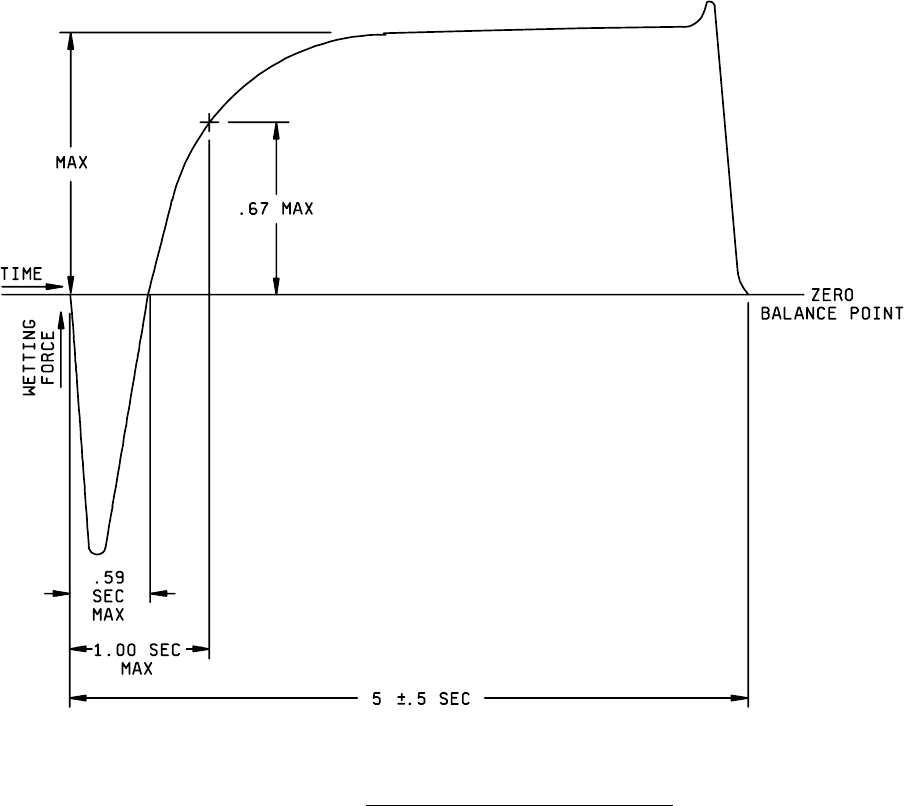
FIGURE 2022-1. Wetting balance curve evaluation criteria
.
MIL-STD-883F
METHOD 2022.2
29 May 1987
4
This page intentionally left blank
MIL-STD-883F
METHOD 2023.5
19 August 1994
1
METHOD 2023.5
NONDESTRUCTIVE BOND PULL
1. PURPOSE
. The purpose of this method is to reveal nonacceptable wire bonds while avoiding damage to acceptable
wire bonds. This procedure is applicable for all bonds made by either ultrasonic or thermal compression techniques, except
those larger than 0.005 inch diameter (or equivalent cross section area) which do not have sufficient clearance to permit use
of a hook.
The alternate procedure defined in 3.2 may be used for devices with packages having 84 or more external terminations and
with nominal bonding wire pitch at the package post of less than or equal to 12 mils.
2. APPARATUS
. The apparatus of this test shall consist of suitable equipment for applying the specified stress to the
bond, lead wire or terminal as required in the specified test condition. A calibrated measurement and indication of the
applied stress in grams force (gf) shall be provided by equipment capable of measuring stresses up to twice the specified
limit value, with an accuracy of ±5 percent or ±0.3 gf, whichever is greater.
a. The diameter of the wire used to make the hook utilized to apply force to the interconnect wire shall be as follows:
Hook diameter
Wire diameter
(x wire dia)
<
0.002 inch 2.0 x min
> 0.002 inch - <
0.005 inch 1.5 x min
> 0.005 inch 1.0 x min
For ribbon wire, use the equivalent round wire diameter which gives the same cross sectional area as the ribbon wire
being tested. Flat portion of hook (horizontal) shall be >
1.25 x the diameter of the wire being tested.
b. The hook shall be smooth and free of defects which could compromise the test results or damage the wire being
pulled.
c. Travel speed of the hook shall be controlled to that impact loading as the hook initially contacts the wire shall be no
more than 20 percent of the specified nondestructive bond pull force.
d. Final hook placement shall be accomplished under observation at 15X minimum magnification. A microscope with
a zoom capability may be used for indexing the hook.
e. The fixturing which holds the package shall allow positioning the hook for optimum force application to the wire.
f. An indicator shall either (1) measure the force required to cause failure of the interconnect; or (2) provide visual
indication that the predetermined load has been applied.
g. The hook shall be in a fixed position which restricts motion along a straight line between each bond, so that it will
not rise to the highest point which could result in a test for only one bond (e.g., as for a ball bond).