MIL- STD-883F 2004 TEST METHOD STANDARD MICROCIRCUITS.pdf - 第374页
MIL-STD-883F METHOD 2023.5 19 August 1994 2 3. PROCEDURE . The t est s hall be c onducted as speci fied i n the appli cable ac quisi tion doc ument, as a sample or as a scr een, and shal l be cons is tent wit h the part …
MIL-STD-883F
METHOD 2023.5
19 August 1994
1
METHOD 2023.5
NONDESTRUCTIVE BOND PULL
1. PURPOSE
. The purpose of this method is to reveal nonacceptable wire bonds while avoiding damage to acceptable
wire bonds. This procedure is applicable for all bonds made by either ultrasonic or thermal compression techniques, except
those larger than 0.005 inch diameter (or equivalent cross section area) which do not have sufficient clearance to permit use
of a hook.
The alternate procedure defined in 3.2 may be used for devices with packages having 84 or more external terminations and
with nominal bonding wire pitch at the package post of less than or equal to 12 mils.
2. APPARATUS
. The apparatus of this test shall consist of suitable equipment for applying the specified stress to the
bond, lead wire or terminal as required in the specified test condition. A calibrated measurement and indication of the
applied stress in grams force (gf) shall be provided by equipment capable of measuring stresses up to twice the specified
limit value, with an accuracy of ±5 percent or ±0.3 gf, whichever is greater.
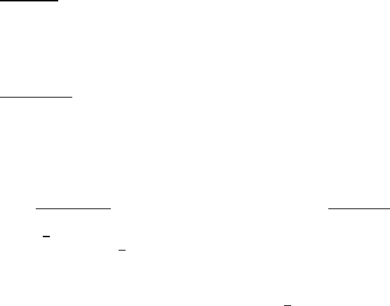
a. The diameter of the wire used to make the hook utilized to apply force to the interconnect wire shall be as follows:
Hook diameter
Wire diameter
(x wire dia)
<
0.002 inch 2.0 x min
> 0.002 inch - <
0.005 inch 1.5 x min
> 0.005 inch 1.0 x min
For ribbon wire, use the equivalent round wire diameter which gives the same cross sectional area as the ribbon wire
being tested. Flat portion of hook (horizontal) shall be >
1.25 x the diameter of the wire being tested.
b. The hook shall be smooth and free of defects which could compromise the test results or damage the wire being
pulled.
c. Travel speed of the hook shall be controlled to that impact loading as the hook initially contacts the wire shall be no
more than 20 percent of the specified nondestructive bond pull force.
d. Final hook placement shall be accomplished under observation at 15X minimum magnification. A microscope with
a zoom capability may be used for indexing the hook.
e. The fixturing which holds the package shall allow positioning the hook for optimum force application to the wire.
f. An indicator shall either (1) measure the force required to cause failure of the interconnect; or (2) provide visual
indication that the predetermined load has been applied.
g. The hook shall be in a fixed position which restricts motion along a straight line between each bond, so that it will
not rise to the highest point which could result in a test for only one bond (e.g., as for a ball bond).

MIL-STD-883F
METHOD 2023.5
19 August 1994
2
3. PROCEDURE. The test shall be conducted as specified in the applicable acquisition document, as a sample or as a
screen, and shall be consistent with the particular bond materials and construction. All bond wires in each device shall be
pulled and counted, and the specified sampling, acceptance, and added sample provisions shall be observed, as applicable.
Where there is any adhesive, encapsulant or other material under, on, or surrounding the wire such as to increase the
apparent bond strength, the test shall be performed prior to the application of the material.
a. Set the rate of force application.
b. Mount the specimen to be tested and set the lifting mechanism to apply the specified force for the appropriate wire
size and material.
c. The device shall be rotated and positioned such that the hook contacts the wire between midspan and loop apex
(for forward wedge and ball bonding, this would be between midspan and die edge; for reverse bonding, this would
be between midspan and package edge) and the pulling force is applied in a direction approximately normal to the
die or substrate, or approximately normal to a straight line between the bonds. The manufacturer should pull as
close to midspan as possible without causing adverse wire deformation.
d. The lifting mechanism shall be actuated to stress the wire bond such that the specified stress is applied with
minimum impact loading and with no overshoot greater than specified accuracy of the indicator at any time during
the bond pull. The dwell time of maximum force application shall be a maximum of one second.
e. Observe whether the bond breaks.
f. If the bond breaks, reject the device and proceed to the next device, unless rework is acceptable. If so, record the
identification of the broken bond and the device containing the bond. If rework is permitted, all bonds shall be
tested prior to any bond rework and reworked bonds shall be tested.
g. If no bonds on the device break, accept the device as satisfactory.
h. Repeat a through g for all bonds to be tested.
i. Record the total number of wires or wire bonds that fail when subjected to the predetermined stress.
j. Record the number of devices that failed the test.
3.1 Failure criteria
. Any bond pull which results in separation (of bonds at the bond interface or breakage of the wire or
interconnect anywhere along the entire span including bond heels) at an applied stress less than the specified stress for the
applicable material and construction shall constitute a failure. Unless otherwise specified, the applied nondestructive pull
stress shall be 80 percent of the preseal minimum bond strengths for the applicable material, size and construction given in
table I of method 2011 or figure 2011-1 of method 2011. Table I herein lists pull force values for commonly used wire sizes.
NOTE: RF/microwave hybrids that require extremely flat loops which may cause erroneous wire pull data may use the
following formula to determine the proper wire pull value.
V
1
= V
2
Sin Θ
Where: V
1
= New value to pull test.
V
2
= Table I value for size wire tested.
Θ = Greatest calculated wire loop angle (figure 2023-1).
MIL-STD-883F
METHOD 2023.5
19 August 1994
3
Also, RF/microwave hybrids that contain tuning wires (designated wires that will alter RF performance when moved) or
wires that cannot be accessed with a pull hook must be simulated on a test coupon in such a way to allow hook access for
purposes of pull testing. These wires are to be bonded at the same time the production hybrids are bonded using the same
setup, operator, schedule, and elements (electrical rejects may be used). The test coupon wires are to be pull tested in lieu
of the tuning or inaccessible wires on the production hybrid. Failures on the test coupon shall be considered as failures to
production units and appropriate action is to be taken in accordance with the applicable specification (figure 2023-2).
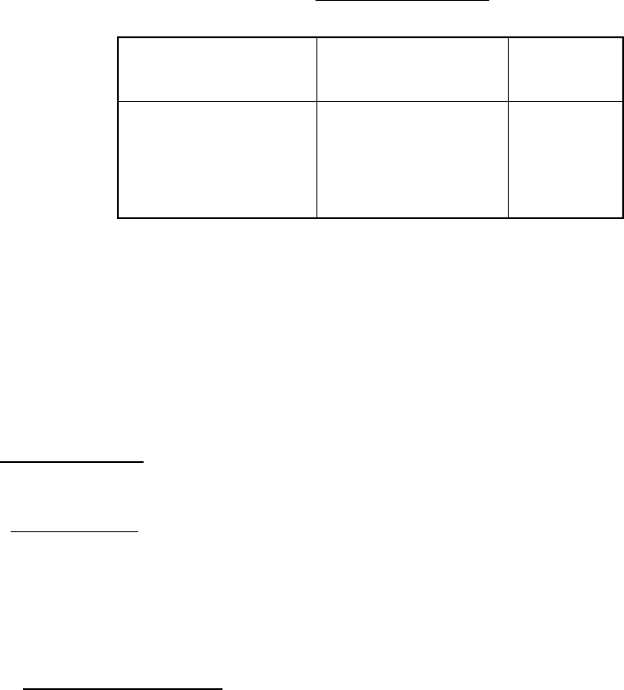
TABLE I. Nondestructive pull forces
.
AL and AU wire
diameter
(inches)
Pull force
(gf)
AL
Pull force
(gf)
AU
0.0007
0.0010
0.00125
0.0013
0.0015
0.0030
1.2
2.0
2.5
2.5
3.0
9.5
1.6
2.4
3.2
3.2
4.0
12.0
NOTES:
1. Nondestructive pull force values for wire sizes not specified
shall be 80 percent of the preseal pull forces for aluminum or
gold wire given in method 2011.
2. Tolerances shall be ±0.3 gf for pull forces up to 6 gf and ±5
percent for pull forces above 6 gf.
3. Any bond subjected to a nondestructive pull force exceeding
the specified pull force and the positive tolerance shall be
eliminated and not counted toward the PDA failures.
3.2 Alternative procedure
. This alternate procedure may be used where 100 percent non-destructive bond pull cannot be
performed because of high pin count (greater than or equal to 84 terminals) and small bonding wire pitch at the package
post (less than or equal to 12 mils).
3.2.1 In-process controls
. In order for a manufacturer to use the alternate procedure, a SPC program shall be
implemented for the wire bond operation in accordance with EIA-557-A, Statistical Process Control Systems. Any change in
the various effects shown to be significant by the characterization with respect to wire bond strength shall require a re-
characterization of the wire bonding process for the changed effect(s) on wire bond integrity. For QML, the SPC program
and the requirements listed herein shall be approved by the qualifying activity and may be subject to an audit at any time by
the government qualification activity. For Non-Jan devices, the SPC program and the requirements listed herein are subject
to review by the government agency responsible for the acquisition or their designee. All statistical evaluation,
characterizations, and designed experiments shall be available for review.
3.2.1.1 Applicable incoming materials
. Applicable incoming materials including wafer pad metallization targets, package
bonding post, and bonding wire shall have their critical characteristics determined and made requirements for acceptance
using either incoming inspection or vendor SPC data. Critical characteristics shall include possible sources of material
contamination (e.g. excessive carbon content in aluminum wire). Also, the applicable incoming inspection requirements of
MIL-PRF-38535 or MIL-PRF-38534 shall apply.