MIL- STD-883F 2004 TEST METHOD STANDARD MICROCIRCUITS.pdf - 第384页
MIL-STD-883F METHOD 2024.2 15 January 1982 2 TABLE I. Mini mum torque l imits versus design s eal area . Design s eal area (cm2) Torque Newton meter (N-m) Inch- pounds for ce (in-lbf) Meter-g rams force (m-gf) <0.22 0…

MIL-STD-883F
METHOD 2024.2
15 January 1982
1
METHOD 2024.2
LID TORQUE FOR GLASS-FRIT-SEALED PACKAGES
1. PURPOSE
. The purpose of this test is to determine the shear strength of the seal of glass-frit-sealed microelectronic
packages. This is a destructive test.
2. APPARATUS
. The test equipment shall consist of suitable fixed or adjustable clamps and fixtures to secure devices
while applying a torque to the seal area. The torque mechanism and holding fixtures should provide adequate support to the
base and lid (especially for flat packs, chip carrier packages, or other thin profile packages) to assure that the torque is
applied predominantly to the seal area without significant bending, warping or displacement of the package being tested. A
torsion wrench or torque-applying mechanism capable of applying a torque of at least 12.8 newton meter (114 in-lbf) with a
gauge capable of measuring the force with an accuracy and precision of ±5 percent of the reading or ±0.2 newton meter,
whichever is greater, shall be used to apply torque to the lid. For smaller seal area packages a torsion wrench or
torque-applying mechanism with sufficient capacity to separate the package and with an accuracy and precision of ±5
percent of the reading or ±0.2 newton meter whichever is greater, may be used to allow for a more accurate reading. The
torque mechanism shall have a peak indicator for retaining the maximum stress applied or other equivalent stress recording
system.
3. PROCEDURE
. The device shall be held by the device body and torque applied to the lid of the device or vice versa.
The lid torque fixtures shall be placed to assure that it only applies torque to the side area of the package lid, base, or
spacer. Contact to the sealing glass should be avoided. The lid torque fixture may touch the package leads but not in such
a way that significant torque is transferred directly through the leads. The torque shall be applied gradually and smoothly
until package separation occurs, or the reaching of the 12.8 newton meter torque limit. The torque required for package
separation or the reaching of the 12.8 newton meter torque limit shall be recorded. The torque shall be applied such that the
axis of rotation is perpendicular to the sealing plane and the axis of rotation shall be located at the geometric center of the
sealing area (see figure 2024-2).
3.1 Separate glass seals
. For packages with more than one glass-frit-seal (e.g., separate glass-frit-seals for the lid and
the lead frame), each seal shall be torqued and rated separately against the failure criteria. A failure of either seal shall
constitute failure of the test. Alternatively, the two seals may be simultaneously stressed by holding only the lid and base
and applying the torque specified for the larger seal area.
3.2 Failure criteria
. A device where package separation or breakage occurs at a torque value less than specified in table
I shall constitute a failure. If the entire package (lid, seal, and base) breaks in a direction normal to the plane of the applied
torque (i.e., showing evidence of improperly applied torque) with parts of lid and base still fused together, the package may
be discarded without counting as a failure and a replacement sample substituted to complete the required testing.
4. SUMMARY
. The following details shall be specified in the applicable acquisition document:
a. The minimum torque if other than the value specified in table I.
b. Number of devices to be tested.
c. Requirement for data recording where applicable.

MIL-STD-883F
METHOD 2024.2
15 January 1982
2
TABLE I. Minimum torque limits versus design seal area.
Design seal area
(cm2)
Torque
Newton meter
(N-m)
Inch-pounds force
(in-lbf)
Meter-grams force
(m-gf)
<0.22
0.221-0.32
0.321-0.47
0.471-0.65
0.651-0.85
0.851-1.08
1.081-1.41
1.411-1.73
1.731-2.05
2.051-2.50
2.501-3.00
>3.00
0.5
0.7
1.0
1.7
2.5
3.4
4.4
5.9
7.4
8.8
10.8
12.8
4
6
9
15
22
30
39
52
65
78
96
114
50
70
100
170
250
350
450
600
750
900
1100
1300
Various units are presented for the convenience of those using conventional
torque wrenches scaled in metric or English system units. All values have been
rounded off from the direct conversion values beginning with N-m and are
acceptable for use in quality conformance and qualification inspection.
1 m-gf = 0.009807 N-m
1 in-lbf = 0.1130 N-m
MIL-STD-883F
METHOD 2024.2
15 January 1982
3
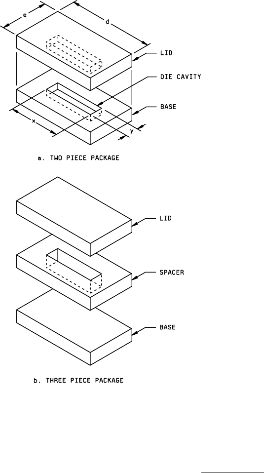
Seal area = ed - xy
If the cavities in the lid and base
are not equal, the area "XY" shall be
determined from the larger of the
cavities in the lid or base.
FIGURE 2024-1. Design seal area
.