MIL- STD-883F 2004 TEST METHOD STANDARD MICROCIRCUITS.pdf - 第39页
MIL-STD-883F METHOD 1005.8 1 June 1993 5 3.5.6. 1 Special c onsi derati ons for devices with int ernal t hermal l imit ation . For devi ces wi th inter nal ther mal shut down, extended exposure at a temper ature i n exce…

MIL-STD-883F
METHOD 1005.8
1 June 1993
4
3.4 Test sample
. The test sample shall be as specified (see 4). When this test method is employed as an add-on life
test for a series or family of device types, lesser quantities of any single device type may be introduced in any single addition
to the total sample quantity, but the results shall not be considered valid until the minimum sample size for each device has
been accumulated. Where all or part of the samples previously under test are extracted upon addition of new samples, the
minimum sample size for each type shall be maintained once that level is initially reached and no sample shall be extracted
until it has accumulated the specified minimum test hours (see 3.1).
3.5 Test conditions
.
3.5.1 Test condition A, steady-state, reverse bias
. This condition is illustrated on figure 1005-1 and is suitable for use on
all types of circuits, both linear and digital. In this test, as many junctions as possible will be reverse biased to the specified
voltage.
3.5.2 Test condition B, steady-state, forward bias
. This test condition is illustrated on figure 1005-1 and can be used on
all digital type circuits and some linear types. In this test, as many junctions as possible will be forward biased as specified.
3.5.3 Test condition C, steady-state, power and reverse bias
. This condition is illustrated on figure 1005-1 and can be
used on all digital type circuits and some linear types where the inputs can be reverse biased and the output can be biased
for maximum power dissipation or vice versa.
3.5.4 Test condition D, parallel excitation
. This test condition is typically illustrated on figure 1005-2 and is suitable for
use on all circuit types. All circuits must be driven with an appropriate signal to simulate, as closely as possible, circuit
application and all circuits shall have maximum load applied. The excitation frequency shall not be less than 60 Hz.
3.5.5 Test condition E, ring oscillator
. This test condition is illustrated on figure 1005-3, with the output of the last circuit
normally connected to the input of the first circuit. The series will be free running at a frequency established by the
propagation delay of each circuit and associated wiring and the frequency shall not be less than 60 Hz. In the case of
circuits which cause phase inversion, an odd number of circuits shall be used. Each circuit in the ring shall be loaded to its
rated maximum. While this condition affords the opportunity to continuously monitor the test for catastrophic failures (i.e.,
ring stoppage), this shall not be considered acceptable as a substitute for the intermediate measurements (see 3.3).
3.5.6 Test condition F, (class level B only) temperature-accelerated test
. In this test condition, microcircuits are
subjected to bias(es) at an ambient test temperature (175°C to 300°C ) which considerably exceeds their maximum rated
temperature. At higher temperatures, it is generally found that microcircuits will not operate normally, and it is therefore
necessary that special attention be given to the choice of bias circuits and conditions to assure that important circuit areas
are adequately biased without damaging overstresses to other areas of the circuit. To properly select the actual biasing
conditions to be used, it is recommended that an adequate sample of devices be exposed to the intended high temperature
while measuring voltage(s) and current(s) at each device terminal to assure that the specified circuit and the applied
electrical stresses do not induce damaging overstresses.
At the manufacturer's option, alternate time and temperature values may be established from table I. Any time-temperature
combination which is contained in table I within the time limit of 30 to 1,000 hours may be used. The life test ground rules of
3.5 of method 1016 shall apply to life tests conducted using test condition F. The applied voltage at any or all terminals shall
be equal to the voltage specified for the 125°C operating life in the applicable acquisition document, unless otherwise
specified.
If necessary, with the specific approval of the qualifying activity, the applied voltage at any or all terminal(s) may be reduced
to not less than 50 percent of the specified value(s) when it is demonstrated that excessive current flow or power dissipation
would result from operation at the specified voltage(s). If the voltage(s) is so reduced, the life test duration shall be
determined by the following formula:
t
o
(100%)
T
a
=
100% - V%
Where T
a
is the adjusted total test duration in hours, t
o
is the original test duration in hours, and V percent is the largest
percentage of voltage reduction made in any specified voltage.

MIL-STD-883F
METHOD 1005.8
1 June 1993
5
3.5.6.1 Special considerations for devices with internal thermal limitation
. For devices with internal thermal shutdown,
extended exposure at a temperature in excess of the shut-down temperature will not provide a realistic indicator of long-term
operating reliability. For such devices, measurement of the case temperature should be made at the specified bias voltages
at several different ambient temperatures. From these measurements, junction temperatures should be computed, and the
operating life shall be performed at that ambient temperature which, with the voltage biases specified, will result in a worst
case junction temperature at least 5°C but no more than 10°C below the minimum junction temperature at which the device
would go into thermal shutdown, and the test time shall be determined from table I for the applicable device class level.
4. SUMMARY. The following details shall be specified in the applicable acquisition document:
a. Special preconditioning, when applicable.
b. Test temperature, and whether ambient, junction, or case, if other than as specified in 3.2.
c. Test duration, if other than as specified in 3.1.
d. Test mounting, if other than normal (see 3).
e. Test condition letter.
f. End-point measurements and intermediate measurements (see 3.3).
g. Criteria for device failure for intermediate and end-point measurements (see 3.3), if other than device
specification limits, and criteria for lot acceptance.
h. Test sample (see 3.4).
i. Time to complete end-point measurements, if other than as specified (see 3.3).
j. Authorization for use of condition F and special maximum test rating for condition F, when applicable (see 4.b).
k. Time temperature conditions for condition F, if other than as specified in 3.5.6.
MIL-STD-883F
METHOD 1005.8
1 June 1993
6
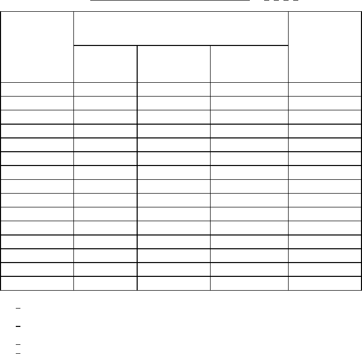
TABLE I. Steady-state time temperature regression
. 1/ 2/ 3/ 4/
Minimum
temperature
T
A
(°C )
Minimum time (hours) Test
condition
(see 3.5)
Class level
S
Class level
B
Class level S
hybrids
(Class K)
100
7500 7500 Hybrid only
105
4500 4500 "
110
3000 3000 "
115
2000 2000 "
120
1500 1500 "
125 1000 1000 1000 A -E
130 900 704 --- "
135 800 496 --- "
140 700 352 --- "
145 600 256 --- "
150 500 184 --- "
175
40 --- F
180
32 --- "
185
31 --- "
190
30 --- "
1
/ Test condition F shall be authorized prior to use and consists of temperatures 175°C
and higher.
2
/ For condition F the maximum junction temperature is unlimited and care shall be taken
to ensure the device(s) does not go into thermal runaway.
3
/ The only allowed conditions are as stated above.
4
/ Test temperatures below 125°C may be used for hybrid circuits only.