MIL- STD-883F 2004 TEST METHOD STANDARD MICROCIRCUITS.pdf - 第40页
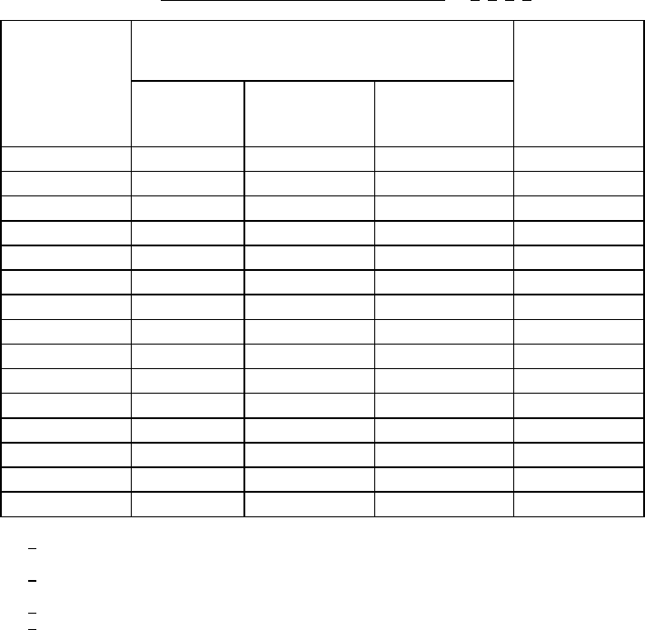
MIL-STD-883F METHOD 1005.8 1 June 1993 6 TABLE I. Steady- stat e time t emperatur e regres sion . 1/ 2/ 3 / 4/ Minimum temperat ure T A (°C ) Minimum ti me (hours ) Test condit ion (see 3. 5) Class le vel S Class le vel …

MIL-STD-883F
METHOD 1005.8
1 June 1993
5
3.5.6.1 Special considerations for devices with internal thermal limitation
. For devices with internal thermal shutdown,
extended exposure at a temperature in excess of the shut-down temperature will not provide a realistic indicator of long-term
operating reliability. For such devices, measurement of the case temperature should be made at the specified bias voltages
at several different ambient temperatures. From these measurements, junction temperatures should be computed, and the
operating life shall be performed at that ambient temperature which, with the voltage biases specified, will result in a worst
case junction temperature at least 5°C but no more than 10°C below the minimum junction temperature at which the device
would go into thermal shutdown, and the test time shall be determined from table I for the applicable device class level.
4. SUMMARY. The following details shall be specified in the applicable acquisition document:
a. Special preconditioning, when applicable.
b. Test temperature, and whether ambient, junction, or case, if other than as specified in 3.2.
c. Test duration, if other than as specified in 3.1.
d. Test mounting, if other than normal (see 3).
e. Test condition letter.
f. End-point measurements and intermediate measurements (see 3.3).
g. Criteria for device failure for intermediate and end-point measurements (see 3.3), if other than device
specification limits, and criteria for lot acceptance.
h. Test sample (see 3.4).
i. Time to complete end-point measurements, if other than as specified (see 3.3).
j. Authorization for use of condition F and special maximum test rating for condition F, when applicable (see 4.b).
k. Time temperature conditions for condition F, if other than as specified in 3.5.6.
MIL-STD-883F
METHOD 1005.8
1 June 1993
6
TABLE I. Steady-state time temperature regression
. 1/ 2/ 3/ 4/
Minimum
temperature
T
A
(°C )
Minimum time (hours) Test
condition
(see 3.5)
Class level
S
Class level
B
Class level S
hybrids
(Class K)
100
7500 7500 Hybrid only
105
4500 4500 "
110
3000 3000 "
115
2000 2000 "
120
1500 1500 "
125 1000 1000 1000 A -E
130 900 704 --- "
135 800 496 --- "
140 700 352 --- "
145 600 256 --- "
150 500 184 --- "
175
40 --- F
180
32 --- "
185
31 --- "
190
30 --- "
1
/ Test condition F shall be authorized prior to use and consists of temperatures 175°C
and higher.
2
/ For condition F the maximum junction temperature is unlimited and care shall be taken
to ensure the device(s) does not go into thermal runaway.
3
/ The only allowed conditions are as stated above.
4
/ Test temperatures below 125°C may be used for hybrid circuits only.
MIL-STD-883F
METHOD 1005.8
1 June 1993
7
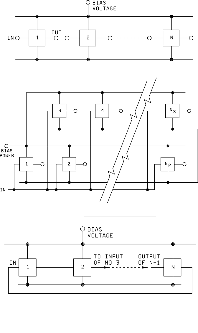
FIGURE 1005-1. Steady-state
.
FIGURE 1005-2. Typical parallel, series excitation
.
NOTE: For free running counter, N is an odd number and the output of N is connect to the input of 1.
FIGURE 1005-3. Ring oscillator
.