MIL- STD-883F 2004 TEST METHOD STANDARD MICROCIRCUITS.pdf - 第408页
MIL-STD-883F METHOD 2032.2 18 June 2004 2 e. Magnif icati on . "High magni fic ation" ins pect ion shall be perfor med perpendic ular t o the element with il luminat ion normal t o the element s urfac e. Other …

MIL-STD-883F
METHOD 2032.2
18 June 2004
1
METHOD 2032.2
VISUAL INSPECTION OF PASSIVE ELEMENTS
1. PURPOSE
. The purpose of this test is to inspect passive elements used for microelectronic applications, including
RF/microwave, for the visual defects described herein. This test can be performed at the unmounted element level, or prior
to sealing or encapsulation, on a 100 percent inspection basis, to detect and eliminate elements with visual defects that
could lead to failure in normal application. It may also be performed on a sample inspection basis at the unmounted element
level, or prior to sealing or encapsulation, to determine the effectiveness of the manufacturer's quality control and handling
procedures for passive elements. Visual inspection criteria are presented in four sections. The first (see 3.1), concerns
planar thin film elements (resistors, capacitors, inductors, single-level patterned substrates and multilevel patterned
substrates). The second (see 3.2), concerns planar thick film elements (resistors, capacitors, single-level patterned hard
substrates, and multilevel patterned hard substrates). The third (see 3.3), concerns nonplanar elements (ceramic chip
capacitors, tantalum chip capacitors, parallel plate chip capacitors, chip resistors, inductors, and transformers). The fourth
(see 3.4) concerns surface acoustic wave (SAW) elements. The inspection criteria contained in each section define the
visual requirements for class H and class K elements (classes of passive elements refer to screening requirements of
MIL-PRF-38534).
2. APPARATUS
. The apparatus for this test shall include optical equipment capable of the specified magnification(s) and
any visual standards (drawings, photographs, etc.) necessary to perform effective inspection and to enable the operator to
make objective decisions as to the acceptability of the element being inspected. Adequate fixturing shall be provided for
handling elements during inspection to promote efficient operation without inflicting damage to them.
3. PROCEDURE
.
a. General
. The element shall be inspected in a suitable sequence of observations within the specified magnification
ranges to determine compliance with class H or class K visual requirements. If a specified visual inspection
requirement is in conflict with element design, topology or construction, it shall be documented and specifically
approved by the acquiring activity. Inspection for all of the visual defect criteria in this test shall be performed on all
elements to which they are applicable. Where a criterion is intended for a specific element type, process, or
technology, it has been so indicated.
b. Sequence of inspection
. The order in which criteria are presented is not a required order of inspection and may be
varied at the discretion of the manufacturer.
c. Inspection control
. In all cases, inspections prior to the final pre-seal inspection shall be performed under the same
quality program that is required at final pre-seal inspection. Care shall be exercised after unmounted element
inspection to prevent any handling induced defects from occurring and to insure that defects created during such
handling will be detected and rejected at final pre-seal inspection. If an element is electrostatic discharge (ESD)
sensitive, then appropriate precautions shall be taken.
d. Inspection environment
. Unmounted element inspection shall be conducted in a 100,000 (0.5 Hm or greater)
particles/cubic foot controlled environment (class 8 of ISO 14644-1), except that the maximum allowable relative
humidity shall not exceed 65 percent. Mounted element inspection shall be conducted in a 100,000 (0.5 Hm or
greater) controlled environment (class 8 of ISO 14644-1) for class H and a 100 (0.5 Hm or greater) controlled
environment (class 5 of ISO 14644-1) for class K. During the time interval between final pre-seal inspection and
preparation for sealing, mounted elements shall be placed in a controlled environment (see 3.i (7)). Both mounted
and unmounted elements shall be in covered containers when transported from one controlled environment to
another.
*
*

MIL-STD-883F
METHOD 2032.2
18 June 2004
2
e. Magnification. "High magnification" inspection shall be performed perpendicular to the element with illumination
normal to the element surface. Other angles at which the inspection can be performed, and at which the element
can be illuminated, may be used at the option of the manufacturer if the visual presentation is the same as used in
the originally specified conditions. "Low magnification" inspection shall be performed with either a monocular,
binocular, or stereo microscope with the element under suitable illumination, tilted at an angle not greater than 30°
from the perpendicular. The magnification ranges to be used for inspection are specified at the start of each
section and are called out at the start of each major criteria grouping.
f. Reinspection
. When inspection for product acceptance or quality verification of the visual requirements herein is
conducted subsequent to the manufacturer's successful inspection, the additional inspection shall be performed at
the magnification specified herein, unless a specific magnification is required by the acquisition document.
g. Exclusions
. Where conditional exclusions have been allowed, specific instruction as to the location and conditions
for which the exclusion can be applied shall be documented in the assembly drawing.
h. Format and conventions
. For ease of understanding and comparison, visual criteria are presented side-by-side in
a columnar format. Class H criterion are presented in the left column and class K criterion are presented in the
right column. When there are differences, the applicable parts of the class H criterion are underlined, for ease of
comparison and clarity, and the differences only are shown in the class K column. When there are similarities, the
phrase "same as class H" is used with no underlining of the class H criterion. If a requirement is not applicable to
either product class, this is indicated by "N/A." A note in the class H column is applicable to class K unless
otherwise specified in the class K column. A note in the class K column is applicable to class K only. Two kinds of
notes are used herein, regular notes (NOTE:) and precautionary notes (PRECAUTIONARY NOTE:). A regular
note is a integral part of a criterion. A precautionary note is not an integral part of the criterion but serves to alert
the user to a requirement of the General Specification for Hybrids, MIL-PRF-38534. The phrases "except by
design," "intended by design," "by design," or "unless otherwise specified by design" require that the element
drawing be referenced to determine intent. For inspections performed at 100X, the criteria of "0.1 mil of
passivation, separation, or metal" is satisfied by a "line of passivation, separation, or metal." Reference herein to
"that exhibits" is satisfied when the visual image or visual appearance of the element under examination indicates a
specific condition is present that does not require confirmation by any other method of testing. When other
methods of test are used to confirm that a defect does not exist, they shall be approved by the acquiring activity. In
the figures, cross-hatched areas represent metallization, blank areas represent resistor material and shaded areas
represent exposed underlying material. The letters "x", "y", or "z" represent the dimension of interest and the letter
"d" represents the original dimension. Most figures show the reject condition only.
i. Definitions
:
(1) Active circuit area
is all functional circuitry, operating metallization, or any connected combinations of these.
In the case of resistors, it includes all resistor material that forms a continuous path between two metallized
areas (usually bonding pads).
(2) Block resistor
is a solid, rectangularly shaped resistor, which, for purposes of trimming, is designed to be
much wider than would be dictated by power density requirements and shall be identified in the approved
manufacturer's precap visual implementation document.
(3) Bonding pad
is a metallized area (usually located along the periphery of the element) at which an electrical
connection is to be made by the user of the element.
(4) Bridging
is complete connection between circuit features not intended to be connected.
(5) Conductive substrate
is one that can conduct electricity. Copper or doped silicon, for example, are
conductive substrates. Alumina and quartz, for example, are nonconductive (insulating) substrates.
MIL-STD-883F
METHOD 2032.2
18 June 2004
3
(6) Contact window is an opening (usually square) through the oxide (or insulating) layer for the purpose of
allowing contact by deposited material to the substrate.
(7) Controlled environment
is one that has 1,000 or fewer (0.5 Hm or greater) particles/cubic foot in a controlled
environment in accordance with the requirements of ISO 14644-1 for a class 6 clean environment, except
that the maximum allowable relative humidity shall not exceed 65 percent.
(8) Corrosion
is the gradual wearing away of metal, usually by chemical action, with the subsequent production
of a corrosion product.
(9) Crazing
is the presence of numerous, minute, interconnected surface cracks.
(10) Crossover
is the transverse crossing of metallization paths, without mutual electrical contact, achieved by
the deposition of an insulating layer between the metallization paths in the area of crossing.
(11) Detritus
is fragments of original or trim-modified resistor or conductor material.
(12) Dielectric
is an insulating material that does not conduct electricity but may be able to sustain an electric
field. It can be used in crossovers, as a passivation or a glassivation, or in capacitors.
(13) Foreign material
is any material that is foreign to the element or any nonforeign material that is displaced
from its original or intended position in the element. It is considered attached when it cannot be removed by
a nominal gas blow (approximately 20 psig) or by an approved cleaning process. Conductive foreign
material is any substance that appears opaque under those conditions of lighting and magnification used in
routine visual inspection. Particles are considered to be embedded in glassivation when there is evidence of
color fringing around the periphery of the particle.
(14) Glassivation
is the top layer(s) of transparent insulating material that covers the active circuit area, including
metallization, but not bonding pads. Crazing is the presence of numerous minute cracks in the glassivation.
Cracks are fissures in the glassivation layer resulting from stress release or poor adhesion. The cracks can
form loops over metallized areas.
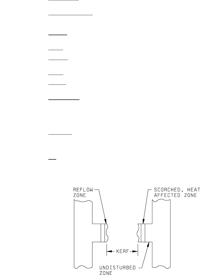
(15) Kerf
is the clear area in a trimmed resistor resulting from the removal of resistor material by the trimming
operation. In laser trimming, the kerf is bounded by the reflow zone (which is characterized by adherent,
melted resistor material), the scorched heat-affected zone (which is characterized by discoloration of the
resistor film without alteration of its physical form), and the undisturbed zone.
*