MIL- STD-883F 2004 TEST METHOD STANDARD MICROCIRCUITS.pdf - 第41页
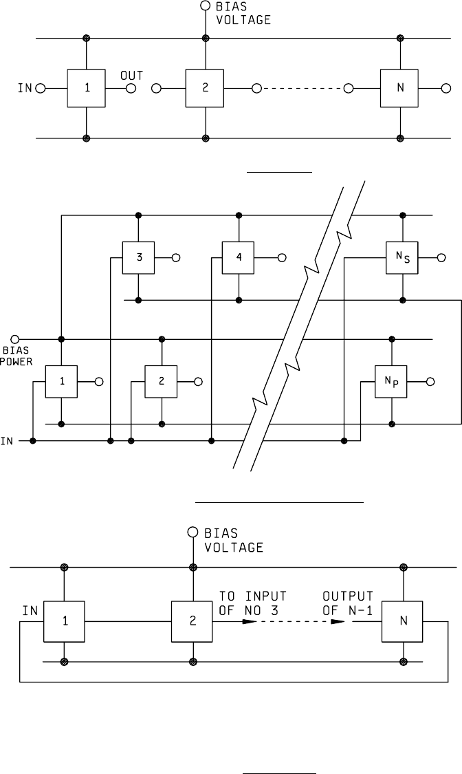
MIL-STD-883F METHOD 1005.8 1 June 1993 7 FIGURE 1005-1. Steady-st ate . FIGURE 1005-2. Typical par allel , ser ies exci tation . NOTE: For f ree runni ng counter , N is an odd number and the output of N is connect to the…
MIL-STD-883F
METHOD 1005.8
1 June 1993
6
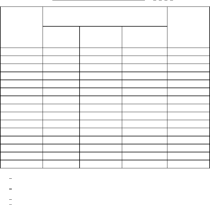
TABLE I. Steady-state time temperature regression
. 1/ 2/ 3/ 4/
Minimum
temperature
T
A
(°C )
Minimum time (hours) Test
condition
(see 3.5)
Class level
S
Class level
B
Class level S
hybrids
(Class K)
100
7500 7500 Hybrid only
105
4500 4500 "
110
3000 3000 "
115
2000 2000 "
120
1500 1500 "
125 1000 1000 1000 A -E
130 900 704 --- "
135 800 496 --- "
140 700 352 --- "
145 600 256 --- "
150 500 184 --- "
175
40 --- F
180
32 --- "
185
31 --- "
190
30 --- "
1
/ Test condition F shall be authorized prior to use and consists of temperatures 175°C
and higher.
2
/ For condition F the maximum junction temperature is unlimited and care shall be taken
to ensure the device(s) does not go into thermal runaway.
3
/ The only allowed conditions are as stated above.
4
/ Test temperatures below 125°C may be used for hybrid circuits only.
MIL-STD-883F
METHOD 1005.8
1 June 1993
7
FIGURE 1005-1. Steady-state
.
FIGURE 1005-2. Typical parallel, series excitation
.
NOTE: For free running counter, N is an odd number and the output of N is connect to the input of 1.
FIGURE 1005-3. Ring oscillator
.
MIL-STD-883F
METHOD 1005.8
1 June 1993
8
This page intentionally left blank