MIL- STD-883F 2004 TEST METHOD STANDARD MICROCIRCUITS.pdf - 第443页
MIL-STD-883F METHOD 2032.2 18 June 2004 37 C lass H Cla ss K 3.1.7 k. ( Continued. ) FIGURE 2032-36h. Class H laser t rim pi tti ng cri terion . 3.1.8 Multileve l thin film de fects, "high magnific ation" . No …
MIL-STD-883F
METHOD 2032.2
18 June 2004
36
Class H Class K
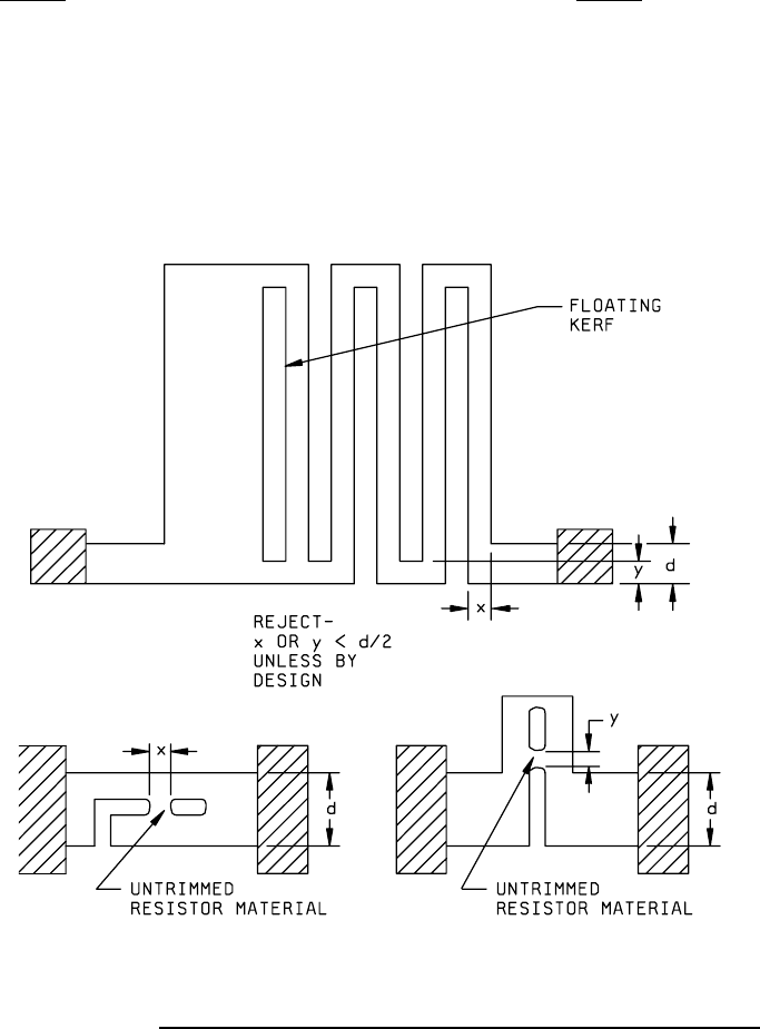
3.1.7 j. A kerf in a resistor that leaves less 3.1.7 j. Same as class H.
than 50 percent of the narrowest resistor
width unless by design (see figure 2032-35h).
NOTE: A floating kerf (one that is completely
contained within the resistor) must meet this
criteria.
PRECAUTIONARY NOTE: The maximum
allowable current density requirement shall
not be exceeded.
FIGURE 2032-35h. Class H resistor width reduction and untrimmed resistor material criteria
.
k. Pits into the silicon dioxide of conductive k. Same as class H.
substrate elements in the kerf which does
not show a line of separation between the
pit and the resistor material (see figure
2032-36h).
MIL-STD-883F
METHOD 2032.2
18 June 2004
37
Class H Class K
3.1.7 k. (Continued.)
FIGURE 2032-36h. Class H laser trim pitting criterion
.
3.1.8 Multilevel thin film defects, "high
magnification"
. No element shall be acceptable
that exhibits:
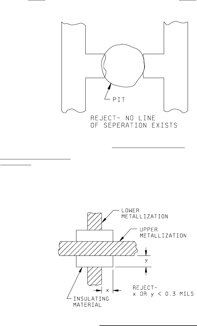
a. Insulating material that does not extend a. Same as class H.
beyond the width of the upper and lower
metallization by 0.3 mil minimum (see
figure 2032-37h).
FIGURE 2032-37h. Class H insulating material extension criteria
.

MIL-STD-883F
METHOD 2032.2
18 June 2004
38
Class H Class K
3.1.8 b. Voids in the insulating material. 3.1.8 b. Same as class H.
c. A bump or indentation in the upper c. Same as class H.
(overlaying) metallization.
NOTE: This criteria is not applicable to
coupling (air) bridges.
d. Scratch that completely crosses the d. Same as class H.
metallization and damages the
insulating material surface on
either side.
3.1.9 Coupling (air) bridge defects "high magnification"
. No element shall be
acceptable that exhibits:
Class H
Class K
a. A void in the coupling (air) bridge a. Same as class H.
metallization that leaves less than 50
percent of the original metallization
width undisturbed. (See figure 2032-37Ah).
b. Nodules or bumps that are greater, in any b. Same as class H.
dimension, than the original coupling (air)
bridge metallization width. (See figure
2032-37Ah).
c. Coupling (air) bridge that contacts under- c. Same as class H.
lying operating metallization. (See figure
2032-37Ah).
d. Attached, conductive foreign material that is d. Same as class H.
greater, in any dimension, than 50 percent
of the original coupling (air) bridge
metallization width.
e. No visible separation between the coupling e. Same as class H.
air) bridge and the underlying operating
metallization.
NOTE: This criterion is not applicable
when an insulating material is used between
the coupling (air) bridge and the underlying
metallization. (See figure 2032-37Ah).
f. Coupling (air) bridge metallization overhang f. Same as class H.
over adjacent operating metallization, not
intended by design, that does not exhibit a
visible separation. (See figure 2032-37Ah).
g. Mechanical damage to a coupling (air) bridge g. Same as class H.
that results in depression (lowering) of
coupling (air) bridge metallization over
underlying operating metallization.