MIL- STD-883F 2004 TEST METHOD STANDARD MICROCIRCUITS.pdf - 第455页
MIL-STD-883F METHOD 2032.2 18 June 2004 49 Cla ss H Class K 3.2. 2 g. An attached por tion of a c irc uit 3.2. 2 g. Same as c lass H. area fr om an adjacent el ement. h. Any c rac k that does not or iginate at an h. Same…
MIL-STD-883F
METHOD 2032.2
18 June 2004
48
Class H Class K
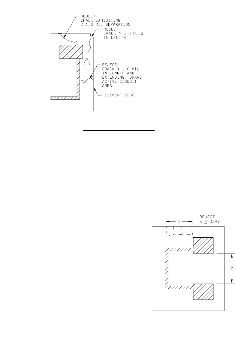
FIGURE 2032-44h. Class H additional crack criteria
.
3.2.2 e. Any crack exceeding 1.0 mil in length 3.2.2 e. Same as class H.
extending from the element edge directly
towards the active circuit area or
operating metallization (see figure
2032-44h).
f. N/A f. Semicircular crack or combination of
cracks along the element edge whose total
length is equal to or greater than 75
percent of the narrowest separation
between any two bonding pads (see figure
2032-45k).
FIGURE 2032-45k. Class K semicircular
crack criterion
.

MIL-STD-883F
METHOD 2032.2
18 June 2004
49
Class H Class K
3.2.2 g. An attached portion of a circuit 3.2.2 g. Same as class H.
area from an adjacent element.
h. Any crack that does not originate at an h. Same as class H.
edge.
i. Holes through the substrate, unless by i. Same as class H.
design.
j. Patterned substrates having a section broken j. Same as class H.
out around a substrate mounting hole
(intended for substrate-to-post attachment)
that is greater than 25 percent of the
mounting hole circumference.
MIL-STD-883F
METHOD 2032.2
18 June 2004
50
Class H Class K
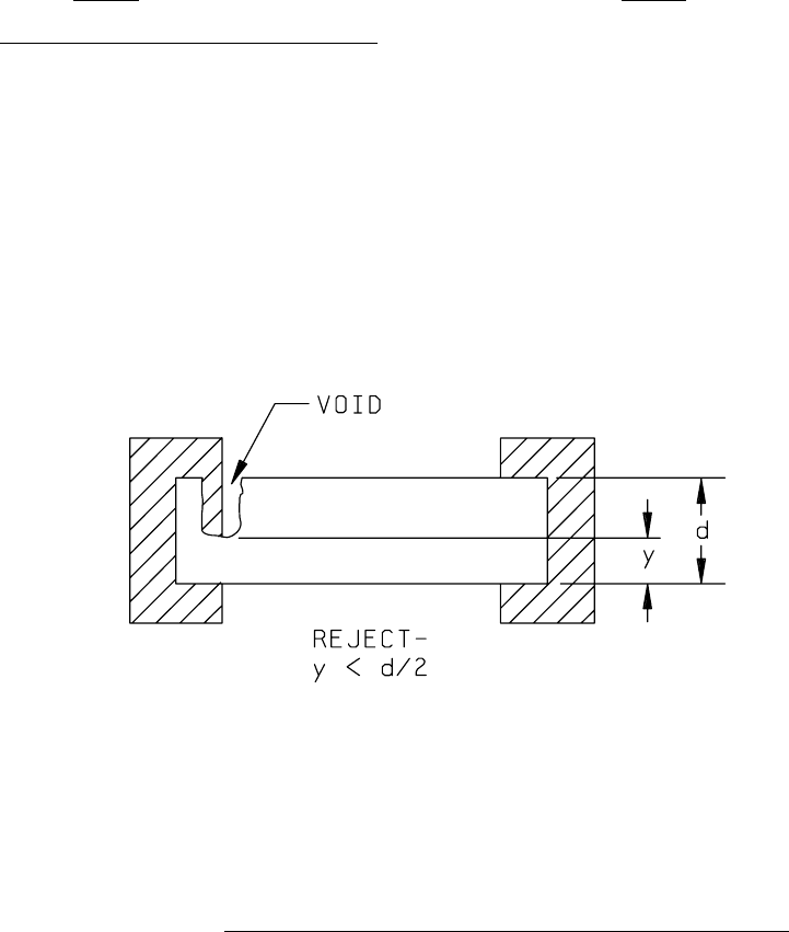
3.2.3 Thick film resistor defects, "low magnification"
.
No element shall be acceptable that exhibits:
a. A reduction of the resistor at the terminal a. Same as Class H.
due to voids to less than 50 percent of the
original resistor width (see figure 2032-46h).
FIGURE 2032-46h. Class H resistor width reduction at terminal caused by voids criterion
.
b. Reduction of the resistor at the terminal, b. Same as Class H.
due to neckdown less than 50 percent, to
of the original resistor width (see figure
2032-47h).