MIL- STD-883F 2004 TEST METHOD STANDARD MICROCIRCUITS.pdf - 第457页
MIL-STD-883F METHOD 2032.2 18 June 2004 51 Cla ss H Class K FIGURE 2032-47h. Class H resi stor width reduc tion at termi nal by neck down cri teri on . 3.2. 3 c . Any r esis tor f ilm l ifti ng, peeli ng, or 3. 2.3 c . S…
MIL-STD-883F
METHOD 2032.2
18 June 2004
50
Class H Class K
3.2.3 Thick film resistor defects, "low magnification"
.
No element shall be acceptable that exhibits:
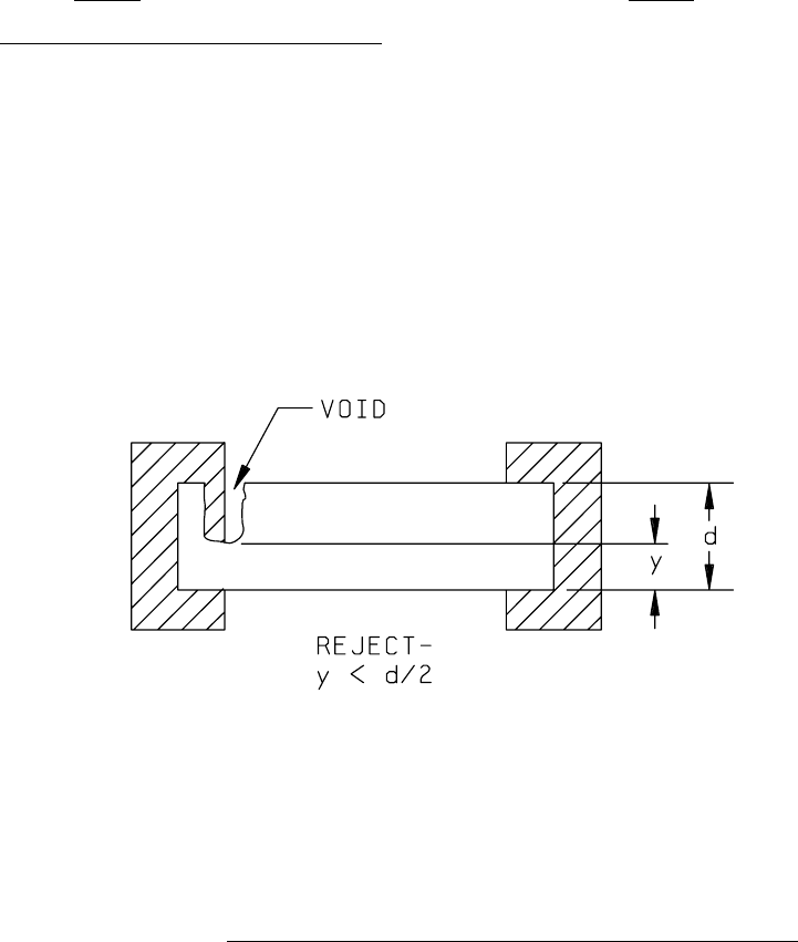
a. A reduction of the resistor at the terminal a. Same as Class H.
due to voids to less than 50 percent of the
original resistor width (see figure 2032-46h).
FIGURE 2032-46h. Class H resistor width reduction at terminal caused by voids criterion
.
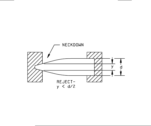
b. Reduction of the resistor at the terminal, b. Same as Class H.
due to neckdown less than 50 percent, to
of the original resistor width (see figure
2032-47h).
MIL-STD-883F
METHOD 2032.2
18 June 2004
51
Class H Class K
FIGURE 2032-47h. Class H resistor width reduction at terminal by neckdown criterion
.
3.2.3 c. Any resistor film lifting, peeling, or 3.2.3 c. Same as class H.
blistering.
d. Crack in the resistor greater than 1.0 mil d. Same as class H.
in length.
NOTE: Irregularities such as fissures in
resistor material that are created during
firing, and that do not expose the
underlying material, are not considered
to be cracks.
e. Evidence of resistor repair by overprinting e. Same as class H.
or any other means.
f. Separation between any two resistors that is f. Same as class H.
less than 50 percent of the original separation.
g. Separation between any resistor and conductor g. Same as class H.
combination that is less than 50 percent of
the original separation.
h. Increase in resistor width greater than 25 h. Same as class H.
percent of the original design width.
i. Resistor that is closer than 1.0 mil to the i. Same as class H.
edge of the substrate.
MIL-STD-883F
METHOD 2032.2
18 June 2004
52
Class H Class K
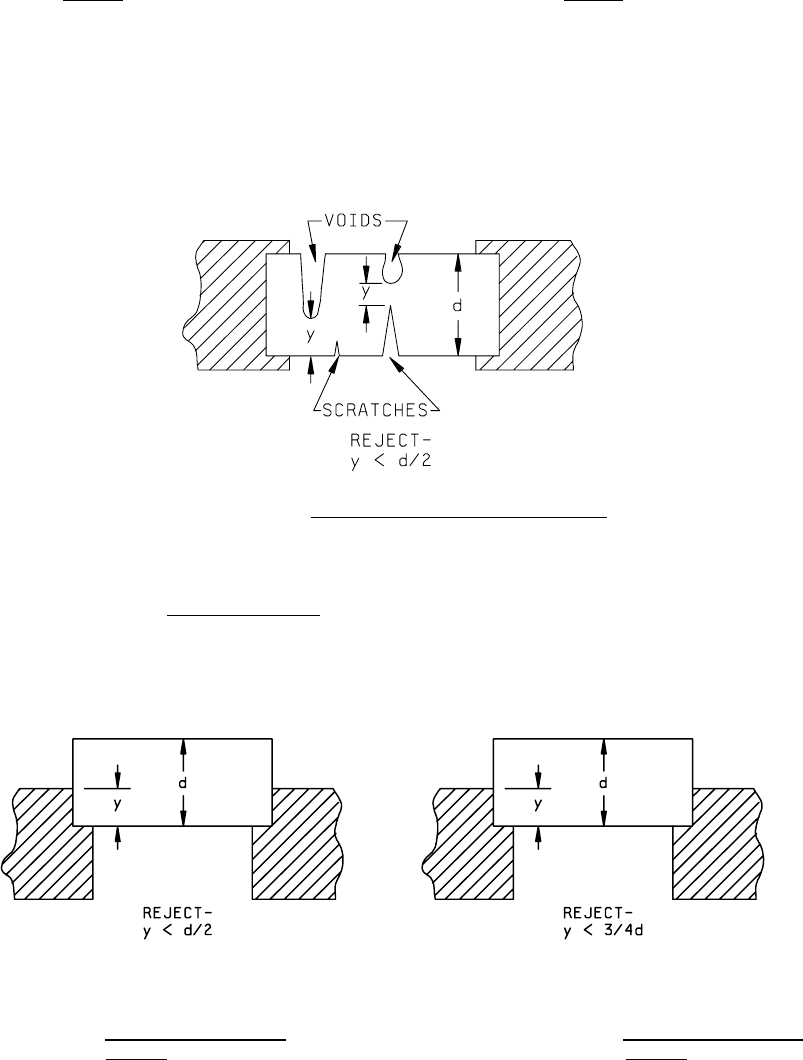
3.2.3 j. Reduction of resistor width resulting from 3.2.3 j. Same as class H.
voids, scratches, or chipouts, or a
combination of these, that leaves less
than 50 percent of the narrowest resistor
width (see figure 2032-48h).
PRECAUTIONARY NOTE: The maximum allowable
current density requirement shall not
be exceeded.
FIGURE 2032-48h. Class H resistor width reduction criteria
.
k. Contact overlap between the metallization k. Less than 75 percent (see
and the resistor in which the actual width figure 2032-49k).
dimension "y" is less than 50 percent
of the
original resistor width (see figure 2032-49h).
FIGURE 2032-49h. Class H resistor overlap
FIGURE 2032-49k. Class K resistor overlap
criterion
. criterion.