MIL- STD-883F 2004 TEST METHOD STANDARD MICROCIRCUITS.pdf - 第475页
MIL-STD-883F METHOD 2035 19 August 1994 3 3.9 Report s of i nspect ion. For clas s S devic es, or when spec ifi ed for other device c las ses, the manufac turer shall furni sh inspec tion r eports with eac h shipment of …

MIL-STD-883F
METHOD 2035
19 August 1994
2
3.1 Calibration of the instrument. When specified, at least one device of the type and construction to be tested shall be
available to set up the ultrasonic inspection equipment and peripherals. The device may be a scape non-operational device
with TAB bonded leads which will be used to identify device landmarks and ensure the equipment is properly functional.
3.2 Labeling and identifying
. The devices tested and the image records made of them shall be labeled in a standard
format to include the following information:
a. Device manufacturer's name or code identification number.
b. Device type or part number.
c. Production lot number and/or inspection date code lot number.
d. Ultrasonic image view number and date; to include description or code for the region or bond
number (s) viewed.
e. Device serial/cross reference number if applicable.
f. Ultrasonic operator identification.
3.3 Serialized devices
. When device serialization is required, each device shall be readily identifiable by a serial number,
and this serial number must be included in a form readable in the stored image. In the event of a skipped piece in the
serialization, a blank space representing the skipped piece, and labeled with its serial number should appear in the storage
medium. In the event of a large contiguous range of skipped pieces, a similar blank space advising of the range of pieces
skipped should appear in the storage medium in place of the large physical space of the many skips.
3.4 Data back-up
. When required, data back-up shall be specified from a choice of multiple floppy disk, multiple track
data tape, or a video format tape, or other options having sufficient volume, resolution, speed, and reliability to suit the
requirements for storage and labeling.
3.5 Mounting
. The devices shall be mounted for ultrasonic inspection in a fixture which insures correct positioning in all
dimensions, and adequately safeguards the potentially fragile bonds from mechanical contact with any substance other than
the coupling fluid. Positioning thereafter must continue in a fashion which continues the above condition, and furthermore
exposes each inspected bond area to the correct acoustic environment and portion of the instrumental field.
3.6 Angle of insonification
. The angle of insonification must be specified by prior analysis, and if the mounting fixture is
goniometrically agile it must be set to the correct angle by adjustment or selection.
3.7 Conditions of operation
. Adjustments, selections, options, and settings used in the performance of the ultrasonic
inspection must be recorded if they are of a nature critical to the proper operation of equipment; not to be recorded are those
casual adjustments which are done as an obvious matter of course, and the performance of which are guided by such rules
as trimming for maximum, minimum, or optimum, and which are not controlled by calibrated interfaces.
3.8 Operating personnel
. Operating personnel shall have a basic familiarity of the nature of sound and the use of
ultrasonic instruments in the inspection of devices. They shall be specifically trained and certified in the operation of the
ultrasound and peripheral equipment used so that defects revealed by the method can be validly interpreted and compared
with applicable standards.

MIL-STD-883F
METHOD 2035
19 August 1994
3
3.9 Reports of inspection. For class S devices, or when specified for other device classes, the manufacturer shall furnish
inspection reports with each shipment of devices. The report shall describe the results from the ultrasonic inspection, and
list the purchase order number, or equivalent identification, the part number, the date code, the quantity inspected, the
quantity rejected, and the date of the test. For each rejected device, the part number, the serial number when applicable,
and the cause for rejection shall be listed.
3.10 Acoustic micrograph and report retention
. When specified, the manufacturer shall retain a set of the ultrasonic
images and a copy of the inspection report, for the period specified.
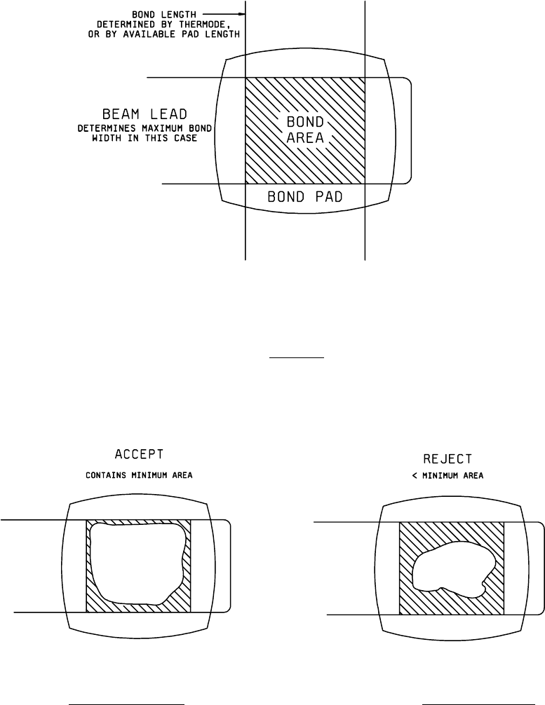
3.11 Examination and acceptance criteria
. Once the manufacturer has established the total bond area to be sought,
based upon studies of the device to be bonded, and the inclusion of a prudent excess margin, then the following shall be
considered the minimum bond area percentage:
a. In the case of solder bonds of lead-tin alloys a bond area percentage of 75 percent of the total bond area shall be
considered minimum.
b. In the case of gold-tin eutectic and gold-gold thermocompression, a bond area percentage of 50 percent of the
total bond area shall be considered minimum, except in the case of lead misalignment; when lead misalignment is
a contributing factor a bond area percentage of 75 percent shall be considered minimum.
In the examination of devices, the following aspects shall be considered unacceptable bonding, and devices which exhibit
any of the following defects shall be rejected:
a. A bond having a total bond area less than the minimum bond area. The failure may be caused by any reason,
including lateral or longitudinal misalignment.
b. A bond meeting the minimum bond area, but with this area being discontinuous so that no single bonded area
meets or exceeds the minimum bond area.
4. Summary
. The following details shall be specified in the applicable acquisition document:
a. Number of views to be taken by SLAM inspection of each piece or bonding site, in accordance with 3.10, if other
than one view.
b. Markings of devices, or labeling of images, if other than in accordance with 3.2, or special markings of devices to
indicate that they have been ultrasonically imaged, if required.
c. Defects to be sought in the devices, and criteria for acceptance or rejection, if other than in 3.11.
d. Image and report retention when applicable (see 3.10).
MIL-STD-883F
METHOD 2035
19 August 1994
4
FIGURE 2035-1. Bond area
.
FIGURE 2035-2. Acceptable bond area
. FIGURE 2035-3. Rejectable bond area.