MIL- STD-883F 2004 TEST METHOD STANDARD MICROCIRCUITS.pdf - 第484页
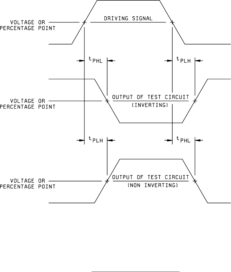
MIL-STD-883F METHOD 3003.1 15 November 1974 2 FIGURE 3003-1. Propagation del ay-posi tive i nput puls e .

MIL-STD-883F
METHOD 3003.1
15 November 1974
1
METHOD 3003.1
DELAY MEASUREMENTS
1. PURPOSE
. This method established the means for measuring propagation delay of digital microelectronic devices,
such as TTL, DTL, RTL, ECL, and MOS.
1.1 Definitions
. The following definitions for the purpose of this test method shall apply.
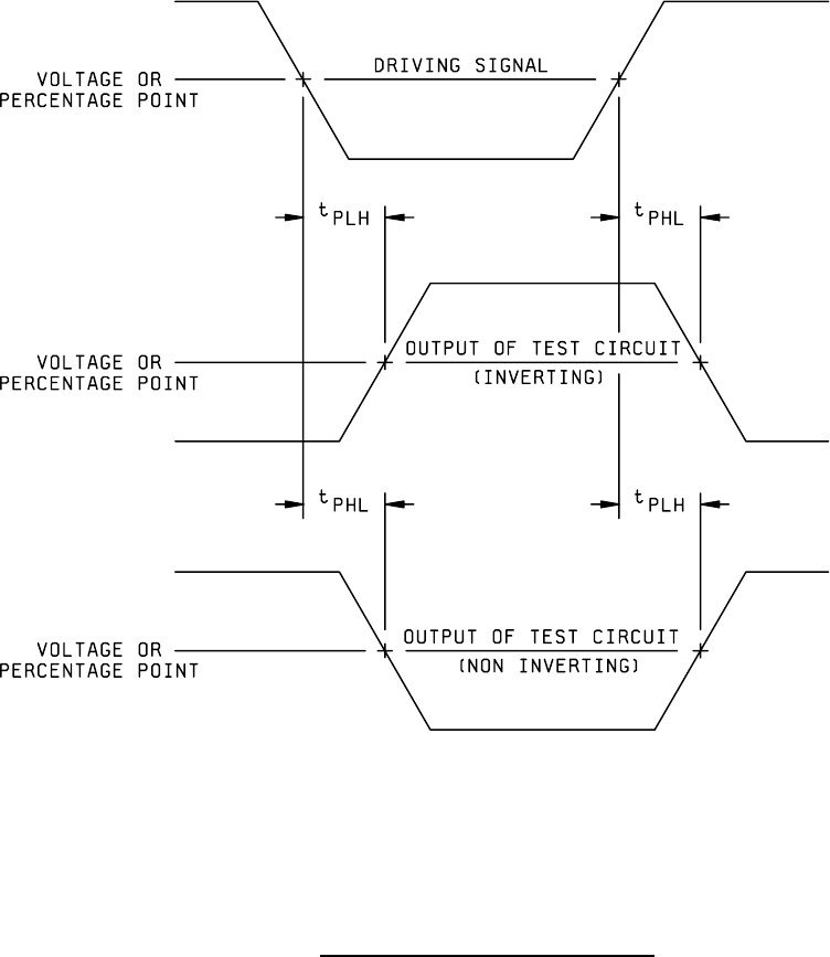
1.1.1 Propagation delay time (t
PHL
). The time measured with the specified output changing from the defined HIGH level to
the defined LOW level with respect to the corresponding input transition.
1.1.2 Propagation delay time (t
PLH
). The time measured with the specified output changing from the defined LOW level to
the defined HIGH level with respect to the corresponding input transition.
2. APPARATUS
. Equipment capable of measuring elapsed time between the input signal and output signal at any
percentage point or voltage point between the maximum LOW level and minimum HIGH level shall be provided. The input
shall be supplied by a driving source as described in method 3001 of this standard. It is desirable for this equipment to have
data logging capability so that circuit dynamic performance can be monitored. The test chamber shall be capable of
maintaining the device under test at any specified temperature.
3. PROCEDURE
. The test circuit shall be loaded according to method 3002 of this standard. The driving signal to the
test circuit shall be provided according to method 3001 of this standard. The device shall be stabilized at the specified test
temperature.
3.1 Measurements at a voltage point
. t
PLH
and t
PHL
shall be measured from the threshold voltage point on the driving
signal to the threshold voltage point on the test circuit output signal for both inverting and noninverting logic. These delays
shall be measured at the input and output terminals of the device under test. The device under test shall be conditioned
according to the applicable acquisition document with nominal bias voltages applied. Figures 3003-1 and 3003-2 show
typical delay measurements.
3.2 Measurements at percentage points
. t
PLH
and t
PHL
shall be measured from a specified percentage point on the driving
signal to a specified percentage point on the test circuit output signal for both inverting and noninverting logic. These delays
shall be measured at the input and output terminals of the device under test. The device under test shall be conditioned
according to the applicable acquisition document with nominal bias voltages applied. Figures 3003-1 and 3003-2 show
typical delay measurements.
4. SUMMARY
. The following details shall be specified in the applicable acquisition document:
a. t
PLH
and t
PHL
limits.
b. Parameters of the driving signal: t
THL
, t
TLH
, high Level, low Level, pulse width, repetition rate.
c. Load conditions.
d. Conditioning voltages (static or dynamic).
e. Measurement points (see 3.1 and 3.2).
f. Power supply voltages.
g. Test temperature.
MIL-STD-883F
METHOD 3003.1
15 November 1974
2
FIGURE 3003-1. Propagation delay-positive input pulse
.
MIL-STD-883F
METHOD 3003.1
15 November 1974
3
FIGURE 3003-2. Propagation delay - negative input pulse
.