MIL- STD-883F 2004 TEST METHOD STANDARD MICROCIRCUITS.pdf - 第52页
MIL-STD-883F METHOD 1009.8 22 March 1989 4 b. Leads mi ssi ng, brok en, or par tial ly separ ated. I n addition, any lead whic h exhibits pinholes , pitt ing, bl ist ering, flak ing, c orros ion produc t that complet ely…

MIL-STD-883F
METHOD 1009.8
22 March 1989
3
NOTE: In cases where two orientations are required for testing, the specified sample size shall be divided in half (or as
close to one-half as possible). In all cases, inspections following the test in accordance with 3.4 shall be
performed on all package surfaces.
NOTE: Precautions may be used to prevent light induced photovoltaic electrolytic effects when testing windowed UV
erasable devices.
3.1.4 Chamber operation
. After conditioning of test chamber in accordance with 3, a salt fog having a temperature of
95°F minimum (35°C minimum) shall be passed through the chamber for the specified test duration (see 3.2). The exposure
zone of the chamber shall be maintained at a temperature of 95°F ±5°F (35°C ±3°C). The fog concentration and velocity
shall be so adjusted that the rate of salt deposit in the test area is between 20,000 and 50,000 mg/m
2
/24 hours. Rate of salt
deposit may be determined by either volumetric, gravimetric, or other techniques at the user's option. The salt solution
collecting at the bottom of the chamber shall be discarded.
3.2 Length of test
. The minimum duration of exposure of the salt atmosphere test shall be specified by indicating a test
condition letter from the following table. Unless otherwise specified, test condition A shall apply:
Test condition
Length of test
A 24 hours
B 48 hours
C 96 hours
D 240 hours
3.3 Preparation of specimens for examination
. Upon completion of the salt exposure test, the test specimens shall be
immediately washed with free flowing deionized water (not warmer than 100°F (38°C) for at least 5 minutes to remove salt
deposits from their surface after which they shall be dried with air or inert gas, and subjected to the inspections below.
3.4 Failure criteria
. All inspections shall be performed at a magnification of 10X to 20X, unless otherwise specified in this
procedure (see 3.4.1b and 3.4.1c).
NOTES:
1. Corrosion stains shall not be considered as part of the defective area of 3.4.1a.
2. Corrosion products resulting from lead corrosion that deposit onto areas other than the lead shall not be
considered as part of the defective area of 3.4.1a.
3. Corrosion at the tips of the leads and corrosion products resulting from such corrosion shall be disregarded.
4. Portions of leads which cannot be further tested in accordance with 3.4.1b, due to geometry or design (such as
standoffs on pin grid arrays or the brazed portion of leads on side-brazed packages), shall be subject to the failure
criteria of 3.4.1a.
3.4.1 Finished product
. No device is acceptable that exhibits:
a. Corrosion defects over more than 5 percent of the area of the finish or base metal of any package element other
than leads such as lid, cap, or case. Corrosion defects to be included in this measurement are: Pitting, blistering,
flaking, and corrosion products. The defective area may be determined by: Comparison with charts or
photographs of known defective areas (see figure 1009-2), direct measurement using a grid or similar measuring
device, or image analysis.

MIL-STD-883F
METHOD 1009.8
22 March 1989
4
b. Leads missing, broken, or partially separated. In addition, any lead which exhibits pinholes, pitting, blistering,
flaking, corrosion product that completely crosses the lead, or any evidence of pinholes, pitting, blistering, flaking,
corrosion product, or corrosion stain at the glass seal shall be further tested as follows:
Bend the lead through 90° at the point of degradation in such a manner that tensile stress is applied to the
defect region. Any lead which breaks or shows fracture of the base metal through greater than 50 percent
of the cross-sectional area of the lead shall be considered a reject. In the case of multiple defects the bend
shall be made at the site exhibiting the worst case corrosion. On packages exhibiting defects on more than
ten leads, bends shall be made on a maximum of ten leads exhibiting the worst case corrosion. The
examination of the fracture shall be performed with a magnification of 30X to 60X.
c. Specified markings, which are missing in whole or in part, faded, smeared, blurred, shifted, or dislodged to the
extent that they are not legible. This examination shall be conducted with normal room lighting and with a
magnification of 1X to 3X.
3.4.2 Package elements
. When this test is performed on package elements or partially assembled packages during
incoming inspection or any time prior to completion of package assembly as an optional quality control gate or as a required
test (see 4.d), no part is acceptable that exhibits:
a. Corrosion defects over more than 1.0 percent of the area of the finish or base metal of lids or over more than 2.5
percent of the area of the finish or base metal of any other package element other than leads (such as case).
Corrosion on areas of the finish or base metal that will not be exposed to surrounding ambient after device
fabrication shall be disregarded. This inspection shall be performed according to the procedure in 3.4.1a.
b. Leads with final lead finish that are rejectable in accordance with 3.4.1b.
4. SUMMARY
. The following details shall be specified in the applicable acquisition document:
a. Test duration, if other than test condition A (see 3.2).
b. Measurements and examinations after test, when applicable for other than visual (see 3.4).
c. Requirement for preconditioning, if applicable, and procedure if other than in 3.1.2.
d. Requirement for incoming inspection of package elements or partially assembled packages (see 3.4.2), when
applicable.
MIL-STD-883F
METHOD 1009.8
22 March 1989
5
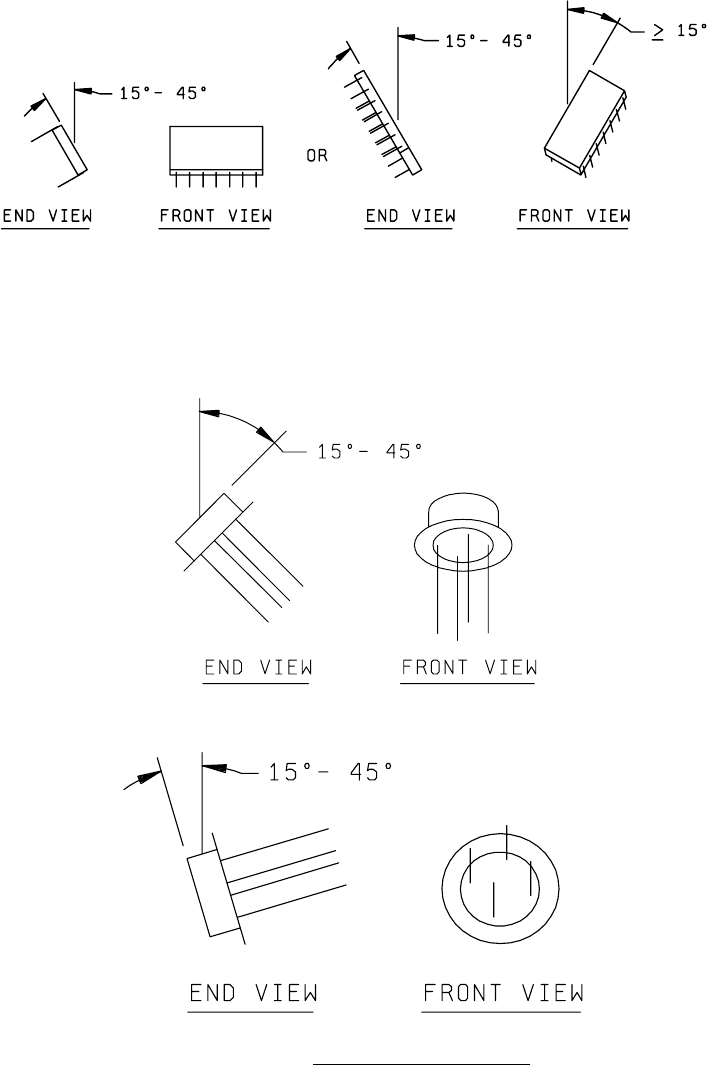
FIGURE 1009-1a. Dual-in-line packages with leads attached to, or exiting from
package sides (such as side-brazed packages and ceramic dual-
in-line packages):
FIGURE 1009-1b. Packages with leads attached to, or exiting from opposite
sides of lids (such as TO cans, solid sidewall packages,
metal platform packages, and pin grid arrays):
1. TO cans:
a. Expose one-half of samples with caps upward:
b. Expose other one-half of samples with leads upward:
FIGURE 1009-1. Example sample orientations
.