MIL- STD-883F 2004 TEST METHOD STANDARD MICROCIRCUITS.pdf - 第528页
MIL-STD-883F METHOD 3017 29 May 1987 6 This page i ntenti onally lef t blank
MIL-STD-883F
METHOD 3017
29 May 1987
5
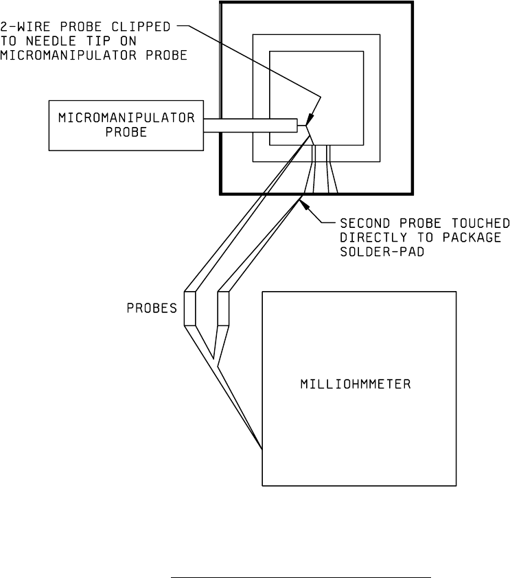
FIGURE 3017-2. Test setup for dc resistance using a milliohmmeter
.
MIL-STD-883F
METHOD 3017
29 May 1987
6
This page intentionally left blank

MIL-STD-883F
METHOD 3018
29 May 1987
1
METHOD 3018
CROSSTALK MEASUREMENTS FOR DIGITAL MICROELECTRONICS DEVICE PACKAGE
1. PURPOSE
. This method establishes the means of measuring the level of cross-coupling of wideband digital signals
and noise between pins in a digital microcircuit package. The method may be used to gather data that are useful in the
prediction of the package's contribution to the noise margin of a digital device. The technique is compatible with multiple
logic families provided that the drive and load impedance are known.
1.1 Definitions
.
1.1.1 Crosstalk
. Signal and noise waveforms coupled between isolated transmission lines, in this case, package
conductors.
1.1.2 Coupling capacitance
. The effective capacitance coupling between a pair of conductors in a package as measured
by the time constant of the charge pulse applied on one line and measured on the other.
1.1.3 Noise pulse voltage
. The voltage of a crosstalk measured at the minimum noise pulse width as measured on a
receiver input line.
1.1.4 Peak noise voltage
. The peak value of the noise pulse measured on a receiver input line.
1.2 Symbols
. The following symbols shall apply for the purpose of this test method and shall be used in accordance with
the definitions provided (see 1.2.1 and 1.2.2).
1.2.1 Logic levels
.
V
OL
(max): The maximum output low level specified in a logic system.
V
OH
(min): The minimum output high level specified in a logic system.
V
IL
(max): The maximum allowed input low voltage level in a logic system.
V
IH
(min): The minimum allowed input high level in a logic system.
1.2.2 Noise pulse width
.
t
PL
: The low level noise pulse width, measured at the V
IL
(max) level (see method 3013).
t
PH
: The high level noise pulse width, measured at the V
IH
(min) level (see method 3012).
1.2.3 Transition times (see method 3004)
.
t
tLH
: Rise time. The transition time of the output from the 10 percent to the 90 percent of the high voltage levels
with the output changing from low to high.
t
tHL
: Fall time. The transition times from the 90 percent to the 10 percent of the high voltage level with the output
changing from high to low.
1.2.4 Crosstalk parameters
.
C
c
: Coupling capacitance (see 1.1.2).
V
N
: Noise pulse voltage (see 1.1.3).
V
NPK
: Peak noise voltage (see 1.1.4).