MIL- STD-883F 2004 TEST METHOD STANDARD MICROCIRCUITS.pdf - 第53页
MIL-STD-883F METHOD 1009.8 22 March 1989 5 FIGURE 1009-1a. Dual-in- line pac kages wi th leads attac hed to, or exiting fr om package s ides (suc h as si de-brazed pac kages and cerami c dual- in-l ine packages ): FIGURE…

MIL-STD-883F
METHOD 1009.8
22 March 1989
4
b. Leads missing, broken, or partially separated. In addition, any lead which exhibits pinholes, pitting, blistering,
flaking, corrosion product that completely crosses the lead, or any evidence of pinholes, pitting, blistering, flaking,
corrosion product, or corrosion stain at the glass seal shall be further tested as follows:
Bend the lead through 90° at the point of degradation in such a manner that tensile stress is applied to the
defect region. Any lead which breaks or shows fracture of the base metal through greater than 50 percent
of the cross-sectional area of the lead shall be considered a reject. In the case of multiple defects the bend
shall be made at the site exhibiting the worst case corrosion. On packages exhibiting defects on more than
ten leads, bends shall be made on a maximum of ten leads exhibiting the worst case corrosion. The
examination of the fracture shall be performed with a magnification of 30X to 60X.
c. Specified markings, which are missing in whole or in part, faded, smeared, blurred, shifted, or dislodged to the
extent that they are not legible. This examination shall be conducted with normal room lighting and with a
magnification of 1X to 3X.
3.4.2 Package elements
. When this test is performed on package elements or partially assembled packages during
incoming inspection or any time prior to completion of package assembly as an optional quality control gate or as a required
test (see 4.d), no part is acceptable that exhibits:
a. Corrosion defects over more than 1.0 percent of the area of the finish or base metal of lids or over more than 2.5
percent of the area of the finish or base metal of any other package element other than leads (such as case).
Corrosion on areas of the finish or base metal that will not be exposed to surrounding ambient after device
fabrication shall be disregarded. This inspection shall be performed according to the procedure in 3.4.1a.
b. Leads with final lead finish that are rejectable in accordance with 3.4.1b.
4. SUMMARY
. The following details shall be specified in the applicable acquisition document:
a. Test duration, if other than test condition A (see 3.2).
b. Measurements and examinations after test, when applicable for other than visual (see 3.4).
c. Requirement for preconditioning, if applicable, and procedure if other than in 3.1.2.
d. Requirement for incoming inspection of package elements or partially assembled packages (see 3.4.2), when
applicable.
MIL-STD-883F
METHOD 1009.8
22 March 1989
5
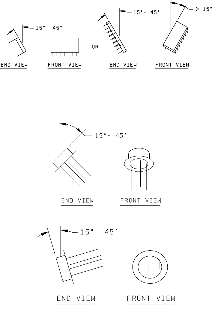
FIGURE 1009-1a. Dual-in-line packages with leads attached to, or exiting from
package sides (such as side-brazed packages and ceramic dual-
in-line packages):
FIGURE 1009-1b. Packages with leads attached to, or exiting from opposite
sides of lids (such as TO cans, solid sidewall packages,
metal platform packages, and pin grid arrays):
1. TO cans:
a. Expose one-half of samples with caps upward:
b. Expose other one-half of samples with leads upward:
FIGURE 1009-1. Example sample orientations
.
MIL-STD-883F
METHOD 1009.8
22 March 1989
6
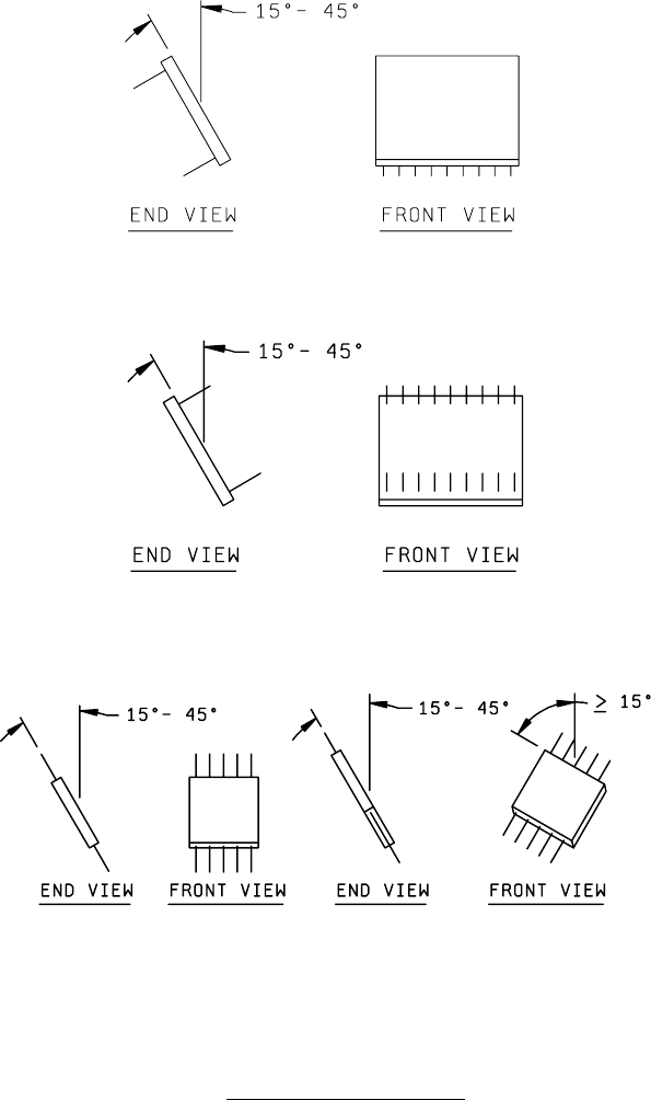
2. Solid sidewall packages, metal platform packages, and pin grid arrays:
a. Expose one-half of samples with lids upward:
b. Expose other one-half of samples with leads upward:
FIGURE 1009-1c. Packages with leads attached to, or exiting from
package sides, parallel to lid (such as flatpacks):
NOTE: If the case is metal, one-half of the samples shall be tested with the
lids exposed upward, the other one-half with the cases exposed upward.
FIGURE 1009-1. Example sample orientations
- Continued.