MIL- STD-883F 2004 TEST METHOD STANDARD MICROCIRCUITS.pdf - 第558页
MIL-STD-883F METHOD 4002.1 22 March 1989 2 4. SUMMARY . The fol lowing detai ls s hall be s pecif ied in t he applic able acqui sit ion document for s pecif ied values of R 1 , R 2 , and V 1 . a. Maximum peak ing. b. Max…

MIL-STD-883F
METHOD 4002.1
22 March 1989
1
METHOD 4002.1
PHASE MARGIN AND SLEW RATE MEASUREMENTS
1. PURPOSE
. This method establishes the means for measuring the stability and slew rate of a linear amplifier intended
to be used with feedback.
1.1 Definitions
. The following definitions shall apply for the purpose of this test method.
1.1.1 Phase margin
. The phase margin is 180° minus the absolute value of the phase shift measured around the loop at
that frequency at which the magnitude of the loop gain is unity. The loop is the series path of the device under test and the
feedback network which is opened at the inverting terminal. The inverting terminal is loaded down to simulate the load
normally presented by the feedback network. Good practice dictates that the phase margin should be at least 45
°.
1.1.2 Peaking
. If a closed loop gain versus frequency plot is made, peaking is the amount by which the gain may increase
over its nominal value just before it falls off. 3 dB of peaking will result from a phase margin of 45
°. Thus, it is desirable to
keep the peaking less than 3 dB.
1.1.3 Slew rate
. Slew rate is the time rate of change of the closed-loop amplifier output voltage under large signal
conditions (i.e., the maximum ac input voltage for which the amplifier performance remains linear). Stabilization networks
will affect the slew rate and therefore these must be included in the measurement.
2. APPARATUS
. The apparatus shall consist of appropriate test equipment capable of measuring specified parameters
and appropriate test fixture with standard input, output, and feedback resistances.
3. PROCEDURE
. The test figures show the connections for the various test conditions. Recommended stabilization
networks should be added to compensate for the degree of feedback in the test. The circuit under test should have
adequate power supply decoupling added. For differential output devices, the measurements described in 3.1 through 3.2.1
below, as applicable, shall be repeated for the other output using the same test figure except an oscilloscope shall be
connected to the other output.
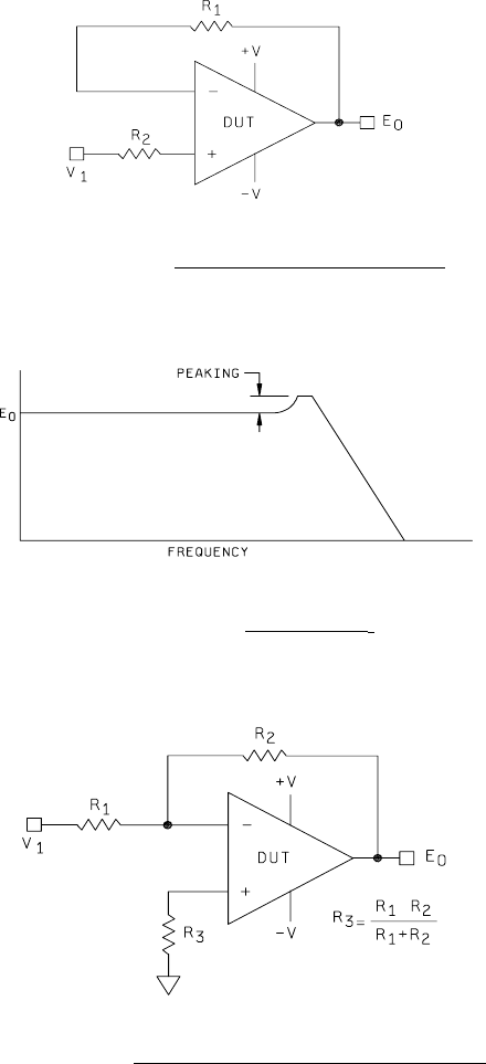
3.1 Phase margin
. The test shall be setup as on figure 4002-1 for a gain of 1 noninverting. This is the maximum
feedback case. R
2
and R
1
shall be the same value and shall be low compared to the amplifier input impedance. Figure
4002-2 shows the amplitude of the envelope of the output E
O
. The peaking shall be less than 3 dB (1.414 times the flat
band voltage) to indicate a 45
° phase margin minimum. The circuit of figure 4002-3 shall be used for single ended inverting
amplifiers (where no positive input terminal is brought out) or where the test is to be run at closed loop gains greater than 1.
Closed loop gain = R
2
/R
1
. In the case of closed loop gains greater than one, the peaking shall be less than 3 dB.
3.2 Pulsed slew rate
. Figure 4002-1 or 4002-3 is the test figure for this test. Values of R
2
and R
1
shall be the same
values as those used in the phase margin test. Stabilization networks shall also be the same. The pulse amplitude V
1
shall
be such that E
0
is the maximum large signal value for the amplifier. With the pulse V
1
having a rise and fall time much faster
than the specified slew rate for the amplifier, the rise and fall time for the amplifier shall be measured and shall be within
specified limits (see 4). The test shall be repeated for both polarities of V
1
.

MIL-STD-883F
METHOD 4002.1
22 March 1989
2
4. SUMMARY
. The following details shall be specified in the applicable acquisition document for specified values of R
1
,
R
2
, and V
1
.
a. Maximum peaking.
b. Maximum rise time for E
0
positive pulses.
c. Maximum fall time for E
0
positive pulses.
d. Maximum rise time for E
0
negative pulses.
e. Maximum fall time for E
0
negative pulses.
f. Test temperature(s). Unless otherwise specified, all parameters shall be measured at the minimum and maximum
specified ambient operating temperatures and at 25°C ambient.
MIL-STD-883F
METHOD 4002.1
22 March 1989
3
FIGURE 4002-1. Test setup noninverting amplifier
.
FIGURE 4002-2. Amplitude of E
o
.
FIGURE 4002-3. Test setup single ended inverting amplifier
.