MIL- STD-883F 2004 TEST METHOD STANDARD MICROCIRCUITS.pdf - 第56页
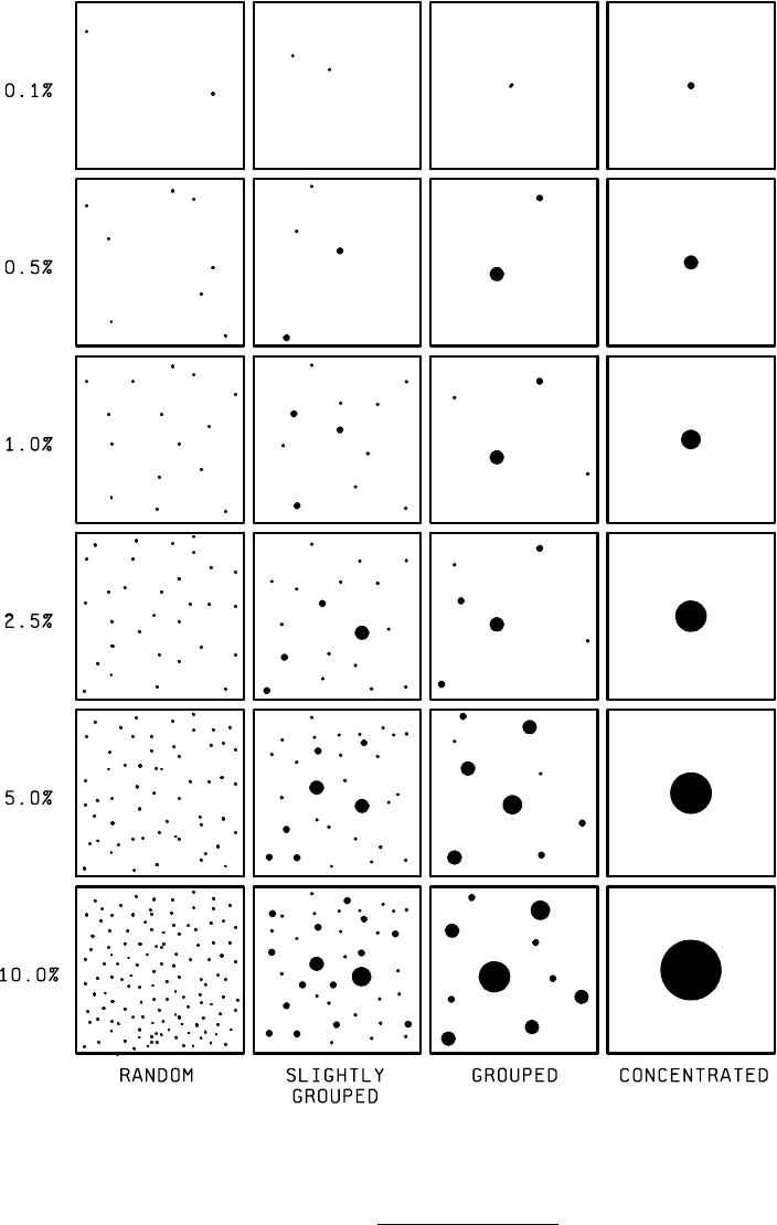
MIL-STD-883F METHOD 1009.8 22 March 1989 8 FIGURE 1009.2. Corros ion area c harts .
MIL-STD-883F
METHOD 1009.8
22 March 1989
7
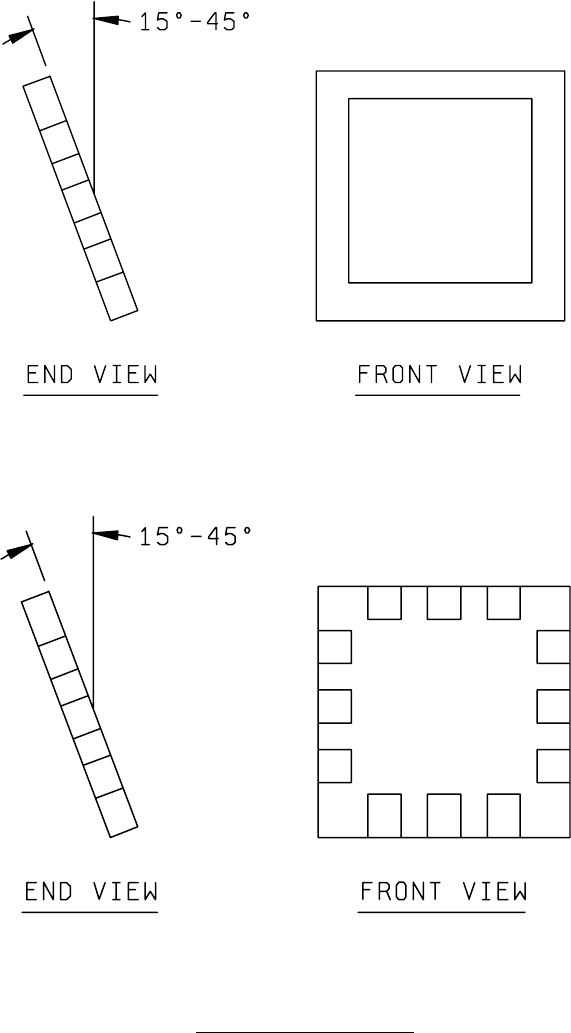
FIGURE 1d. Leadless or leaded chip carriers:
1. Expose one-half of samples with lids upward:
2. Expose other one-half of samples with lids downward:
FIGURE 1009-1. Example sample orientations
- Continued.
MIL-STD-883F
METHOD 1009.8
22 March 1989
8
FIGURE 1009.2. Corrosion area charts
.

MIL-STD-883F
METHOD 1010.8
18 June 2004
1
METHOD 1010.8
TEMPERATURE CYCLING
1. PURPOSE
. This test is conducted to determine the resistance of a part to extremes of high and low temperatures, and
to the effect of alternate exposures to these extremes.
1.1 Terms and definitions
.
1.1.1 Load
. The specimens under test and the fixtures holding those specimens during the test. Maximum load shall be
determined by using the worst case load temperature with specific specimen loading. Monolithic (single block) loads used
to simulate loading may not be appropriate when air circulation is reduced by load configuration. The maximum loading
must meet the specified conditions.
1.1.2 Monitoring sensor
. The temperature sensor that is located to indicate the same temperature as that of the worst
case indicator specimen location. The worst case indicator specimen location is identified during the periodic
characterization of the worst case load temperature.
1.1.3 Worst case load temperature
. The temperature of specific specimens or equivalent mass as indicated by
thermocouples imbedded in their bodies. These indictor specimens shall be located at the center and at each corner of the
load. The worst case load temperature (point which reaches temperature last) is determined at periodic intervals.
1.1.4 Working zone
. The volume in the chamber(s) in which the temperature of the load is controlled within the limits
specified in table I.
1.1.5 Specimen
. The device or individual piece being tested.
1.1.6 Transfer time
. The elapsed time between initiation of load transition (for a single chamber or specimen removal for
multiple chambers) from one temperature extreme and introduction into the other temperature.
1.1.7 Maximum load
. The largest load for which the worst case load temperature meets the timing requirements.
1.1.8 Dwell time
. The time from introduction of the load to one extreme environment temperature until the initiation of the
transfer to the other extreme temperature environment.
2. APPARATUS
. The chamber(s) used shall be capable of providing and controlling the specified temperatures in the
working zone(s) when the chamber is loaded with a maximum load. The thermal capacity and air circulation must enable
the working zone and loads to meet the specified conditions and timing (see 3.1). Worst case load temperature shall be
continually monitored during test by indicators or recorders. Direct heat conduction to specimens shall be minimized.
3. PROCEDURE
. Specimens shall be placed in such a position with respect to the airstream that there is substantially
no obstruction to the flow of air across and around the specimen. When special mounting is required, it shall be specified.
The specimen shall then be subjected to the specified condition for the specified number of cycles performed continuously.
This test shall be conducted for a minimum of 10 cycles using test condition C (see Figure 1010-1). One cycle consists of
steps 1 and 2 or the applicable test condition and must be completed without interruption to be counted as a cycle.
Completion of the total number of cycles specified for the test may be interrupted for the purpose of test chamber loading or
unloading of device lots or as the result of power or equipment failure. However, if the number of interruptions for any
reason exceeds 10 percent of the total number of cycles specified, the test must be restarted from the beginning.
3.1 Timing
. The total transfer time from hot to cold or from cold to hot shall not exceed one minute (for multiple
chambers). The load may be transferred when the worst case load temperature is within the limits specified in table I.
However, the dwell time shall not be less than 10 minutes and the load shall reach the specified temperature within 15
minutes (16 minutes for single chamber).
*
*
*
*
*
*
*
*
*
*