MIL- STD-883F 2004 TEST METHOD STANDARD MICROCIRCUITS.pdf - 第563页
MIL-STD-883F METHOD 4003.1 22 March 1989 3 4. SUMMARY . The followi ng details shal l be spec ified i n the appli cable ac quisi tion doc ument for speci fied val ues of C 1 , C 2 , R 1 , R 2 , R L, and ±V CC for t he nu…

MIL-STD-883F
METHOD 4003.1
22 March 1989
2
3.1 Common mode input voltage range.
3.1.1 Differential input amplifier
. This test shall be an implied measurement. The maximum common mode input voltage
specified for the amplifier shall be used in making the common mode rejection ratio test of 3.2.
3.2 Common mode rejection ratio
.
CMRR
A
A
D
C
=
where A
D
= differential gain, and A
C
= common-mode gain.
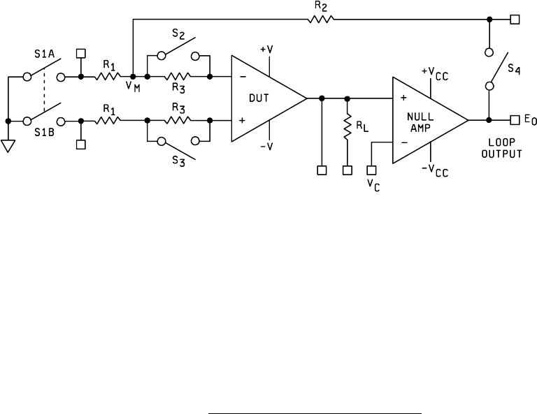
3.2.1 Differential input amplifier using null loop
. The test figure is shown on figure 4003-1, all switches are closed. Raise
V+, V-, and V
C
to V
CM
volts above nominal (i.e., if V+ = 15, V- = -15, V
C
= 0, V
CM
= 10, then set V+ = 25, V- = -5, and V
C
=
10). Measure E
01
. Lower V+, V-, and V
C
to V
CM
volts below nominal. Measure E
02
.
CMRR = 20
R
R
(
E
-
E
)
V
1
2
01 02
CM
log
∆
3.3 Power supply rejection ratio
.
3.3.1 Differential input amplifier
. The power supply shall be adjusted for a value equal to the average of the maximum and
minimum allowable supply voltage. The signal generator connected to the power supply under test shall be adjusted such
that the voltage input at the amplifier under test swings between maximum and minimum specified values. Then:
PSRR = 20
R
R
(
V
)
V
1
2
O
CC
log
∆
∆
where: V
0
= Change in output voltage (peak)
V
CC
= Change in supply voltage (peak)
The frequency used shall be as specified.
3.3.2 Differential input amplifier using null loop
. The test figure is shown on figure 4003-1. Set V
C
to zero. For +PSRR
set V- to constant voltage and set V+ to minimum value and measure E
01
; set the V+ supplies to maximum values and
measure E
02
.
+ PSRR = 20
R
R
(
E
-
E
)
DV
1
2
02 01
CC
log
where DV
CC
is the total change in power supply voltage (if the supplies vary from +5 to +20 V, DV
CC
= 20 - 5 = 15 V). For
-PSRR repeat the above measures with V+ supply held constant and V- varied between the minimum and the maximum
value, measure E
03
and E
04
respectively.
- PSRR = 20
R
R
(
E
-
E
)
DV
1
2
04 03
CC
log

MIL-STD-883F
METHOD 4003.1
22 March 1989
3
4. SUMMARY. The following details shall be specified in the applicable acquisition document for specified values of C
1
,
C
2
, R
1
, R
2
, R
L,
and ±V
CC
for the nulling amplifier.
a. V
CM
at specified temperature(s).
b. CMRR at specified temperature(s). V
I
signal frequency when applicable.
c. PSRR, when applicable, at specified temperature(s).
d. Test temperature(s). Unless otherwise specified, all parameters shall be measured at the minimum and maximum
specified ambient operating temperature and at 25°C ambient.
MIL-STD-883F
METHOD 4003.1
22 March 1989
4
FIGURE 4003-1. Differential input amplifier using null loop
.