MIL- STD-883F 2004 TEST METHOD STANDARD MICROCIRCUITS.pdf - 第567页
MIL-STD-883F METHOD 4004.1 22 March 1989 3 FIGURE 4004-1. Test f igure for bandwidth and i nput impedanc e . FIGURE 4004-2. Transf er func tion ci rcui t .

MIL-STD-883F
METHOD 4004.1
22 March 1989
2
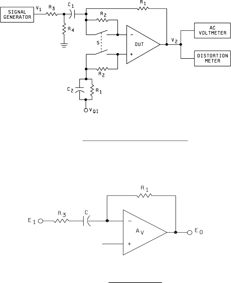
3.4 Bandwidth. Establish the amplitude of V
2
within the linear region of the device under test at a frequency specified for
the measurement of A
D
. Increase the frequency, while maintaining the amplifier of V
1
constant, until V
2
reduces to 0.707 of
the original value (3 dB down). This frequency shall be measured as the bandwidth for the device under test. The test
figure is shown on figure 4004-1.
3.5 Input impedance
. This will be specified as a minimum value and shall be measured by observing that the output
voltage V
2
does not drop more than 6 dB (2:1 in voltage) when the switch S is opened. This test shall be performed at the
specified frequency with a specific amplitude of V
2
within the linear region. R
2
shall be given as the value of the minimum
input impedance. The test figure is shown on figure 4004-1.
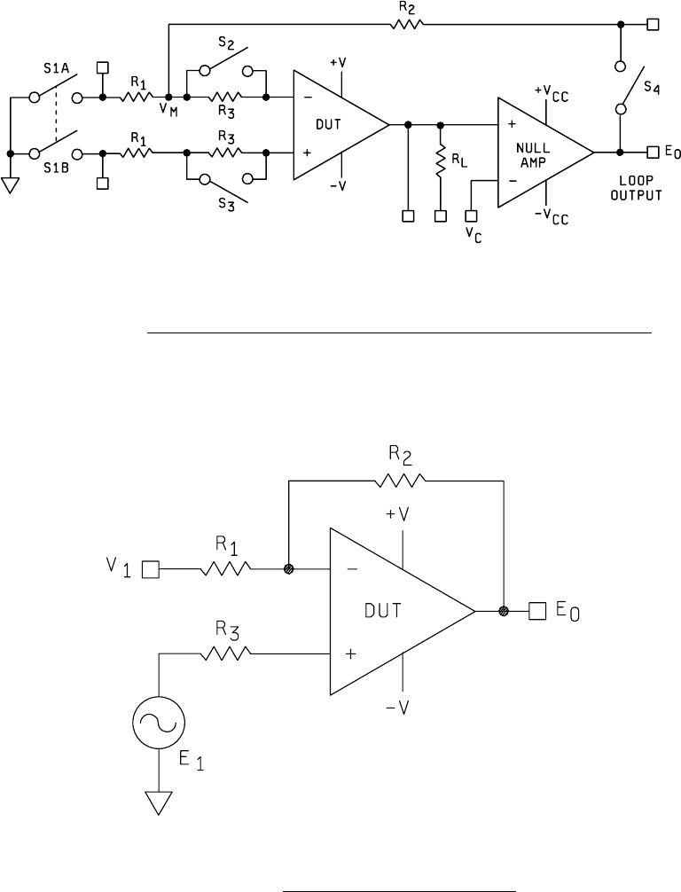
3.6 Unity gain bandwidth
. Increase the frequency of e
I
(starting at 100 kHz) until e
0
= e
I
. The frequency at which this
occurs is GBW. The test figure is shown on figure 4004-4. Set the input voltage V
1
to the required device voltage.
4. SUMMARY
. The following details shall be specified in the applicable acquisition document for specified values of R
1
,
R
2
, C, ±V
CC
for the nulling amplifier, R
3
and R
L
.
a. V
OP
, at specified temperature(s).
b. Z
IN
(minimum), at specified temperature(s) and frequency.
c. Z
DI
, where applicable, at specified temperature(s) and frequency.
d. A
VS
, where applicable, at specified temperature(s) and frequency.
e. A
V
, at specified temperature(s) and frequency.
f. BW
01
, at specified temperature(s).
g. Distortion (%), at specified temperature(s).
h. V
QI
, when applicable, at specified temperature(s).
i. GBW, at specified temperatures.
j. Test temperature(s). Unless otherwise specified, all parameters shall be measured at the minimum and maximum
specified ambient operating temperatures and at 25°C ambient.
MIL-STD-883F
METHOD 4004.1
22 March 1989
3
FIGURE 4004-1. Test figure for bandwidth and input impedance
.
FIGURE 4004-2. Transfer function circuit
.
MIL-STD-883F
METHOD 4004.1
22 March 1989
4
FIGURE 4004-3. Test setup for open loop gain, distortion and maximum output voltage swing
.
FIGURE 4004-4. Test setup for unity gain bandwidth
.