MIL- STD-883F 2004 TEST METHOD STANDARD MICROCIRCUITS.pdf - 第574页
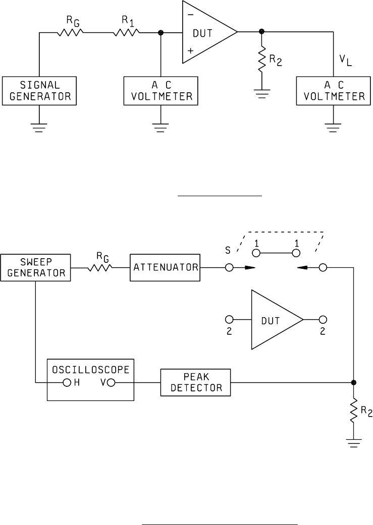
MIL-STD-883F METHOD 4006.1 22 March 1989 4 FIGURE 4006-1. Power gain test cir cuit . FIGURE 4006-2. Power gain tes t ci rcui t (i nsert ion method) .

MIL-STD-883F
METHOD 4006.1
22 March 1989
3
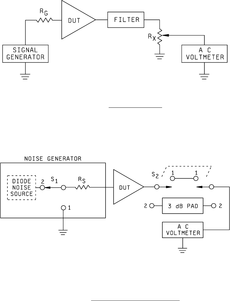
3.3. Noise figure. Figure 4006-3 is used for this test. The input noise voltage shall be calculated from the following
expression:
IN G
N
= 4KT f
R
∆±
where: K = Boltzmann's constant (1.38 x 10
-23
joules/°K)
T = Temperature (
°K)
∆f = Noise bandwidth
R
G
= Source resistance
The input signal level is then set to ten times (20 dB) N
IN
. R
X
is now adjusted so that the ac voltmeter reads 10 dB on some
convenient scale. The input signal V
G
is then reduced to zero and the reduction in dB on the output recorded. The noise
figure NF is obtained by subtracting this drop in dB from 20 dB. The error in this measurement can be calculated from the
following expression:
Error (dB) = 10
V
N
+1 - 20
V
N
2
OUT
OUT
OUT
OUT
log log
⎛
⎝
⎜
⎞
⎠
⎟
⎡
⎣
⎢
⎢
⎤
⎦
⎥
⎥
It should be noted that the error will always be in a direction to indicate a lower noise figure than the true noise figure.
3.4 Noise figure, alternate method
. In this test, a diode noise generator, as shown on figure 4006-4, is used to measure
the noise figure. In this test, with switches S
1
and S
2
in position 1 and the source resistance (R
S
) adjusted to a specified
value, a reference voltage is read on the ac voltmeter. The switches S
1
and S
2
are then moved to position 2 and the diode
source current (I) increased until the previous reference level is read on the ac voltmeter. Using the value of I and R
S
, the
noise figure is determined for the following expression:
NF = 10 Log 20 IR
S
The accuracy of this technique is established by the accuracy of the 3 dB pad and the current meter in the noise diode
circuit.
3.5 Noise factor
. The noise factor can be determined from the following expression:
NF = 10 Log F
In this expression, NF is in dB and F is a numeric.
4. SUMMARY
. The following details shall be specified in the applicable acquisition document for
specified values of R
2
and R
G
:
a. PG, at specified temperature(s) and frequency, and R
2
.
b. NF, at specified temperature(s) and frequency.
c. F, at specified temperature(s) and frequency.
d. Test temperature(s). Unless otherwise specified, all parameters shall be measured at the minimum and maximum
specified ambient operating temperatures and at 25°C ambient.
e. Noise bandwidth (
∆f) (see 3.3).
f. R
S
(see 3.4).
g. R and R
2
, when applicable (see 3.1).
MIL-STD-883F
METHOD 4006.1
22 March 1989
4
FIGURE 4006-1. Power gain test circuit
.
FIGURE 4006-2. Power gain test circuit (insertion method)
.
MIL-STD-883F
METHOD 4006.1
22 March 1989
5
FIGURE 4006-3. Noise figure test circuit
.
FIGURE 4006-4. Noise figure (double power technique)
.