MIL- STD-883F 2004 TEST METHOD STANDARD MICROCIRCUITS.pdf - 第61页
MIL-STD-883F METHOD 1011.9 27 July 1990 1 METHOD 1011.9 THERMAL SHOCK 1. PURPOSE . The purpos e of thi s tes t is to deter mine the r esis tance of the part to sudden exposur e to extreme changes in temper ature and the …
MIL-STD-883F
METHOD 1010.8
18 June 2004
4
This page intentionally left blank

MIL-STD-883F
METHOD 1011.9
27 July 1990
1
METHOD 1011.9
THERMAL SHOCK
1. PURPOSE
. The purpose of this test is to determine the resistance of the part to sudden exposure to extreme changes
in temperature and the effect of alternate exposures to these extremes.
1.1 Terms and definitions
.
1.1.1 Cycle
. A cycle consists of starting at ambient room temperature, proceeding to step 1, then to step 2, or alternately
proceeding to step 2, then to step 1, and then back to ambient room temperature without interruption.
1.1.2 Dwell time
. The total time the load is immersed in the bath.
1.1.3 Load
. The devices under test and the fixture holding these devices.
1.1.4 Maximum load
. The maximum mass of devices and fixtures that can be placed in the bath while maintaining
specified temperatures and times.
1.1.5 Specimen
. The device or individual piece being tested.
1.1.6 Transfer time
. The elapsed time measured from removal of the load from one bath until insertion in the other bath.
1.1.7 Worst case load temperature
. The body temperature of a specific device located at the center of the load.
1.1.8 Monitoring sensor
. The temperature sensor that is located and calibrated so as to indicate the same temperature
as at the worst case indicator specimen location. The worst case indicator specimen location is identified during the periodic
characterization of the worst case load temperature.
2. APPARATUS
. The baths used shall be capable of providing and controlling the specified temperatures in the working
zone(s) when the bath is loaded with a maximum load. The thermal capacity and liquid circulation must enable the working
zone and loads to meet the specified conditions and timing (see 3.1). Worst case load temperature shall be continually
monitored during test by indicators or recorders reading the monitoring sensor(s). The worst case load temperature under
maximum load conditions and configuration shall be verified as needed to validate bath performance. Perfluorocarbons that
meet the physical property requirements of table II shall be used for conditions B and C.
3. PROCEDURE
. Specimens shall be placed in the bath in a position so that the flow of liquid across and around them is
substantially unobstructed. The load shall then be subjected to condition B or as otherwise specified (see 4b) of table I for a
duration of 15 cycles. Completion of the total number of cycles specified for the test may be interrupted for the purpose of
loading or unloading of device lots or as the result of power or equipment failure. However, if the number of interruptions for
any given test exceeds 10 percent of the total number of cycles specified, the test must be restarted from the beginning.
3.1 Timing
. The total transfer time from hot to cold or from cold to hot shall not exceed 10 seconds. The load may be
transferred when the worst case load temperature is within the limits specified in table I. However, the dwell time shall be
not less than 2 minutes and the load shall reach the specified temperature within 5 minutes.
MIL-STD-883F
METHOD 1011.9
27 July 1990
2
3.2 Examination. After completion of the final cycle, an external visual examination of the marking shall be performed
without magnification or with a viewer having a magnification no greater than 3X and a visual examination of the case, leads,
or seals shall be performed at a magnification between 10X and 20X except the magnification for examination shall be 1.5X
minimum when this method is used for 100 percent screening. This examination and any additional specified
measurements and examination shall be made after completion of the final cycle or upon completion of group, sequence, or
subgroup of tests which include this test.
3.3 Failure criteria
. After subjection to the test, failure of any specified end-point measurements or examinations (see
4d), evidence of defects or damage to the case, leads, or seals, or illegible markings shall be considered a failure. Damage
to marking caused by fixturing or handling during tests shall not be cause for device rejection.
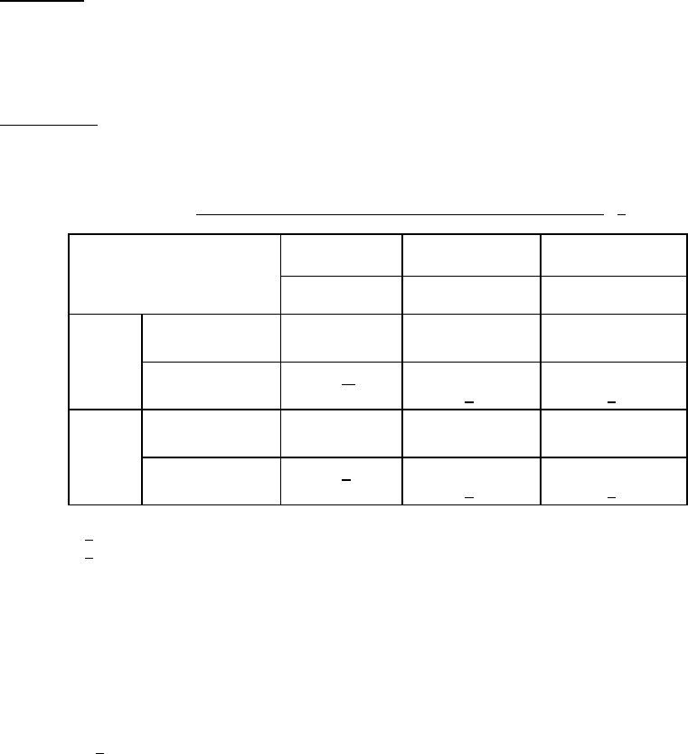
TABLE I. Thermal shock temperature tolerances and suggested fluids
. 1/
Test
conditions
A B C
Temperature Temperature Temperature
Step 1 Temperature
tolerance, °C
100 +10
-2
125 +10
-0
150 +10
-0
Recommended
fluid
Water 2
/ Perfluorocarbon
3
/
Perfluorocarbon
3/
Step 2 Temperature
tolerance, °C
-0 +2
-10
-55 +0
-10
-65 +0
-10
Recommended
fluid
Water 2
/ Perfluorocarbon
3
/
Perfluorocarbon
3/
1
/ Ethylene glycol shall- not be used as a thermal shock test fluid.
2
/ Water is indicated as an acceptable fluid for this temperature
range. Its suitability chemically shall be established prior
to use. When water is used as the fluid for condition A and the
specified temperature tolerances are insufficient due to
altitude considerations, the following alternate test conditions
may be used:
a. Temperature: 100°C -6°C, 0°C +6°C.
b. Cycles shall be increased to 20.
3
/ Perfluorocarbons contain no chlorine or hydrogen.