MIL- STD-883F 2004 TEST METHOD STANDARD MICROCIRCUITS.pdf - 第634页
MIL-STD-883F METHOD 5006 20 November 1969 2 3.1.1 Ther mal evaluati on . This test shall be perfor med in acc ordance wi th method 1012, t est c onditi on B. W i th maximum power appli ed, the c omplete temper ature gr a…
MIL-STD-883F
METHOD 5006
20 November 1969
1
METHOD 5006
LIMIT TESTING
1. PURPOSE
. This method provides means for establishing or evaluating the maximum capabilities of microelectronic
devices, including such capabilities as absolute maximum ratings (from which safe design limits may be derived), maximum
stresses which may be applied in screening or testing without causing degradation, and sensitivity to particular screening or
testing without causing degradation, and sensitivity to particular screening or testing stresses and the associated modes or
mechanisms of failure. Since this is a relatively expensive and time consuming procedure, it is not intended for general
application to all device acquisitions. It should however be extremely useful in evaluating the capabilities of new device
types or devices which have experienced significant modifications in design, materials or processes which might be
expected to alter their stress tolerance or primary modes and mechanisms of failure. It should also be useful in providing
information vital to quality and reliability assurance in high reliability programs or in acquisition extending over significant
periods of time where test results can be used to provide corrective action in device design, processing or testing.
1.1 Destructive testing
. All limit testing accomplished in accordance with this method is considered destructive and
devices shall be removed from their respective lot.
1.2 Parameter measurements
. Electrical measurement shall be performed to remove defective devices after each stress
step unless otherwise specified herein or in the applicable acquisition document. These measurements need not include all
device parameters, but shall include sufficient measurements to detect all electrically defective devices. When delta
parameter measurements are required they shall be specified in the applicable acquisition document.
2. APPARATUS
. The apparatus for this test shall include equipment specified in the referenced test methods as
applicable and electrical measurement equipment necessary to determine device performance.
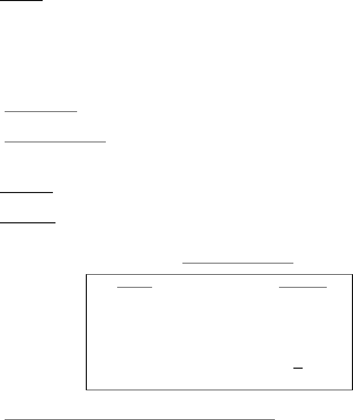
3. PROCEDURE
. Limit testing shall be conducted in accordance with the procedure contained in 3.1 and 3.2 using
samples sizes as designated in table I.
TABLE I. Sample sizes for limit testing
.
Limit test
Thermal evaluation
Extended thermal shock
Step-stress mechanical shock
Step-stress constant acceleration
Step-stress operational life
Constant high stress operational life
Step-stress storage life
Sample size
5
10
10
10
10
10
10
Total devices 65
3.1 Test condition A. Procedure for monolithic and multichip microcircuits
. Limit testing shall be conducted as described
in 3.1.1 through 3.1.7 in the sequence shown, unless otherwise specified (see 4.). Failure analysis of all devices failing limit
tests shall be performed in accordance with method 5003, test condition B, unless otherwise specified in the applicable
acquisition document. Limit testing may be discontinued prior to completing the test when 50 percent of the test sample has
failed that specific test.
MIL-STD-883F
METHOD 5006
20 November 1969
2
3.1.1 Thermal evaluation. This test shall be performed in accordance with method 1012, test condition B. With maximum
power applied, the complete temperature gradient of the active chip area shall be recorded. This data shall be analyzed to
determine that no areas of abnormally high operating temperatures are present as a result of improper design or processing.
The thermal resistance at the maximum operating temperature of the device shall be determined using test condition C or
method 1012.
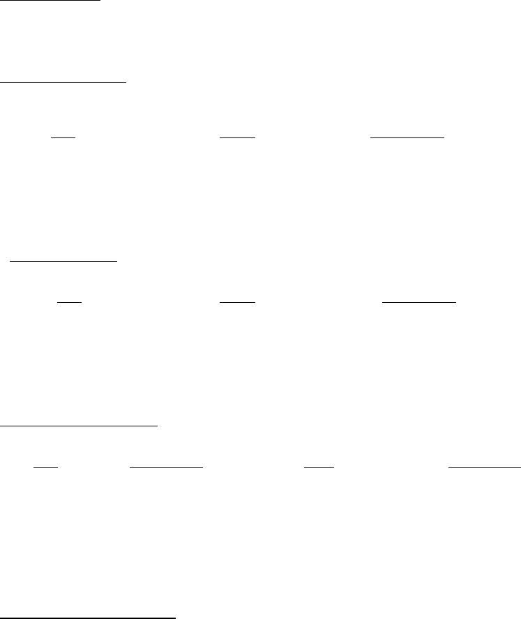
3.1.2 Extended thermal shock
. The purpose of this testing is to establish the resistance of the device to thermal fatigue
effects. The device shall be subjected to a minimum of 100 cycles of thermal shock, in accordance with method 1011. This
test shall be conducted in the following sequence:
Step
Cycles Test condition
1 15 C
2 15 D
3 70 F
Parameter measurements (see 1.2) shall be made at the completion of 15, 30, 40, 70, and 100 cycles, and the number of
failures after each of these cycles shall be recorded.
3.1.2.1 Temperature cycling
. When specified in the applicable acquisition document, temperature cycling method 1010
may be substituted for the thermal shock test in 3.1.2. This test shall be conducted in the following sequence:
Step
Cycles Test condition
1 20 B
2 20 C
3 20 D
Parameter measurements (see 1.2) shall be made at the completion of each step, and the number of failures for each of
these steps shall be recorded.
3.1.3 Step-stress mechanical shock
. The purpose of this test is to establish the mechanical integrity of the device. The
device shall be subjected to mechanical shock in accordance with method 2002 and the following step-stress sequence:
Step
Test condition Plane No. of shocks
1 B Y
1
5
2 C Y
1
5
3 E Y
1
5
4 F Y
1
5
5 G Y
1
5
Electrical parameter measurements (see 1.2) shall be made after each step, and the number of failures incurred at each
step shall be recorded.
3.1.4 Step-stress constant acceleration
. The purpose of this testing is to establish the mechanical integrity of the device.
The device shall be subjected to a constant acceleration in accordance with method 2001 and the following step-stress
sequence:

MIL-STD-883F
METHOD 5006
20 November 1969
3
Step Test condition Plane
1 E Y
2
, X
1
, Z
1
, Y
1
2 F Y
2
, X
1
, Z
1
, Y
1
3 G Y
2
, X
1
, Z
1
, Y
1
4 H Y
2
, X
1
, Z
1
, Y
1
Electrical parameter measurements (see 1.2) shall be made after each plane, and the number of failures incurred shall be
recorded.
3.1.5 Step-stress operational life
. The purpose of this test is to establish the operational stress levels that will accelerate
predominant failure mechanisms so that meaningful failures can be generated in a relatively short period of time. The
results of the testing will also be utilized to evaluate the safety factors built into the device, to establish the safe constant
operational stress conditions, and to improve through corrective action(s) the reliability of the device. Electrical parameter
measurements shall be made after each stress level and the number of failures incurred in each step shall be recorded.
3.1.6 Constant high-stress operational life
. The purpose of this test is to induce meaningful operational failures in a
relatively short period of time and to compare the results of this testing with the results obtained from the step-stress
operational life. The stress level to be applied and intervals to intermediate electrical measurements shall be determined on
the basis of the results obtained in the step-stress tests (see 3.1.5). Electrical parameter measurements shall be made after
each specified time interval and the number of failures shall be recorded.
3.1.7 Step-stress storage life
. The purpose of this test is to establish the storage stress levels that will accelerate
predominant failure mechanisms so that meaningful failures can be generated in a relatively short period of time. The
storage temperatures and the step duration shall be established prior to initiation of testing. The results of the testing will be
utilized to evaluate the maximum limits of device resistance to failure at high temperature. Electrical parameter
measurements shall be made after each stress level and the number of failures incurred at each level shall be recorded.
3.2 Test condition B. Procedure for film and hybrid microcircuits
. Limit test shall be conducted in accordance with table I
and as described in 3.1.1 through 3.1.7 except that the specified test condition may be changed. When test condition or
stress levels are changed, they shall be established prior to the initiation of test. Failure analysis of all devices failing limit
tests shall be performed in accordance with method 5003, test condition B, unless otherwise specified in the applicable
acquisition document. Unless otherwise specified in the applicable acquisition document, limit testing in any test may be
discontinued after 50 percent of test sample has failed that specific test.
3.3 Test plan
. When required by the applicable acquisition document, the specific procedures for conducting limit testing
shall be submitted as a "Limit Test Plan" for approval by the acquiring activity prior to the initiation of testing. This plan shall
include the following as a minimum:
a. Activity responsible for performing the test.
b. Device types to be subjected to limit testing and criteria for their selection.
c. Failure criteria including electrical parameters to be measured.
d. Testing schedule.
e. Description of testing equipment.
f. Test condition if other than specified.
g. Data recording and reporting formats.
h. Data analysis procedures.