MIL- STD-883F 2004 TEST METHOD STANDARD MICROCIRCUITS.pdf - 第666页
MIL-STD-883F METHOD 5010.4 18 June 2004 16 TABL E VIII. Gr oup E (radiat ion hardn ess ass uranc e tests ) . 1/ Test MIL- STD-883 Class le vel S Class le vel B Method Conditi on Quantity/ accept number Notes Quantit y/ a…
MIL-STD-883F
METHOD 5010.4
18 June 2004
15
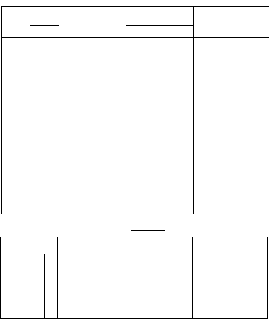
TABLE VI. Group C testing
.
Subgroup
Class
levels
Test MIL-STD-883 Sample size
number,
accept number
Referenced
paragraph
S B
Method Condition
1 X
X
X
X
X
X
X
X
X
X
X
X
X
External
Temperature cycling
Mechanical shock or
constant acceleration
Seal (fine and gross)
Radiographic
Visual examination
End point electrical
2009
1010
2002
2001
1014
2012
C
100 cycles
minimum
B, Y1 axis
E, Y1 axis
Y axis
In accordance
with visual
criteria of
method 1010.
As specified
in accordance
with device
specification
Sample size
number = 15
C = 0
3.4.13
3.4.5
3.4.6
3.4.8
3.4.12
3.5.2.3
2 X X Steady-state life test
End point electrical
1005 1,000 hours
at +125°C
minimum
As specified
in accordance
with device
specification
Sample size
number = 22
C = 0
3.5.2.3
TABLE VII. Group D testing
.
Subgroup
Class Test
MIL-STD-883 Quantity/
accept
number
Referenced
paragraph
S B
Method Condition
1 X X Internal water vapor
content
5000 PPM maximum water
content at +100°C
1018
3 devices
(0 failures)
or
5 devices
(1 failure)
2 X X Moisture resistance 1004
5 (0)
3 X X Salt atmosphere 1009
5 (0)
MIL-STD-883F
METHOD 5010.4
18 June 2004
16
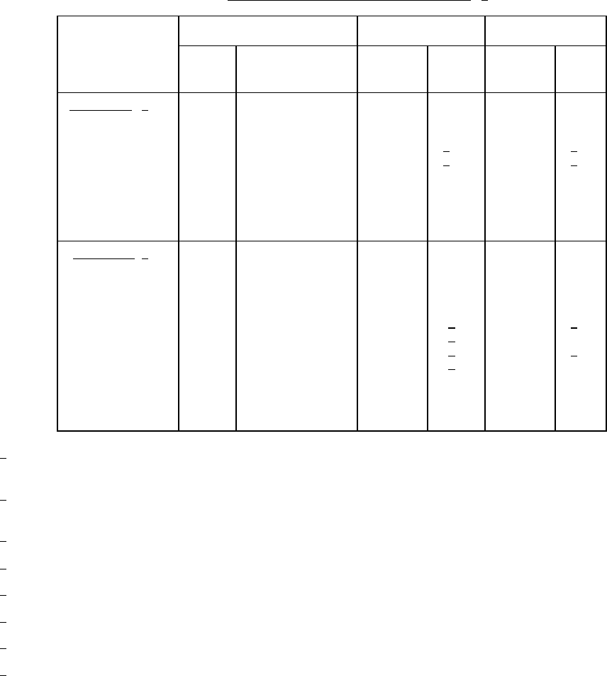
TABLE VIII. Group E (radiation hardness assurance tests). 1/
Test
MIL-STD-883 Class level S Class level B
Method
Condition Quantity/
accept
number
Notes
Quantity/
accept
number
Notes
Subgroup 1 2/
Neutron irradiation
a. Qualification
b. QCI
Endpoint electrical
parameters
1017
+25°C
As specified in
accordance with
device
specification
a. 11 (0)
b. 11 (0)
3
/
3
/
a. 11 (0)
b. 11 (0)
4
/
4
/
Subgroup 2 5/
Steady-state total
dose irradiation
a. Qualification
b. QCI
Endpoint electrical
parameters
1019
+25°C
Maximum supply
voltage
As specified in
accordance with
device
specification
a. 4 (0)
2 (0)
b. 4 (0)
2 (0)
a. 6
/
8
/
b. 6
/
8
/
a. 22 (0)
b. 22 (0)
7
/
7
/
1
/ Parts used for one subgroup test may not be used for other subgroups but may be used for higher levels in the same
subgroup. Total exposure shall not be considered cumulative unless testing is performed within the time limits of the
test method.
2
/ Waive neutron test for MOS IC devices except where neutron susceptibility is less than 10
13
neutrons/cm
2
(e.g.,
charge coupled devices, BICMOS, ect.). Where testing is required, the limit for neutron fluence shall be 2x10
12
neutrons/cm
2
.
3
/ Per wafer lot. If one part fails, seven additional parts may be added to the test sample with no additional failures
allowed, 18(1).
4
/ Per inspection lot. If one part fails, seven additional parts may be added to the test sample with no additional failures
allowed, 18(1).
5
/ Class level B devices shall be inspected using either the class level B quantity/accept number criteria as specified, or
by using the class level S criteria on each wafer.
6
/ Per wafer for device types with less than or equal to 4,000 equivalent transistors/chip selected from the wafer at a
radius approximately equal to two-thirds of the wafer radius, and spaced uniformly around this radius.
7
/ Per inspection lot. If one part fails, 16 additional parts may be added to the test sample with no additional failures
allowed, 38(1).
8
/ Per wafer for device types with greater than 4,000 equivalent transistor/chip selected from the wafer at a radius
approximately equal to two-thirds of the wafer radius and spaced uniformly around this radius.

MIL-STD-883F
METHOD 5010.4
18 June 2004
17
(3) The verifying party shall stamp or sign the lot traveler to attest that the above data meets the test
requirements and that all of the above items were performed and were found to be acceptable.
(4) Failure of the verification test shall require, as a minimum, engineering to perform a detailed review of
hardware/software/set up and parts. If engineering locates the problem, a one time only 100 percent retest
to all group A requirements for all devices that were under consideration for acceptance shall be required.
If the engineering review does not locate the problem, the verification unit shall undergo failure analysis
before retesting the lot.
(a) If failure analysis locates the problem, the entire group of devices being considered for acceptance at
the time of the failure may be retested for appropriate subgroup(s) acceptance one time only by
repeating this group A method.
(b) If the failure analysis does not specifically locate the problem, the lot may be considered for
acceptance one time only by 100 percent retesting of all the devices of the group A requirements and
by repeating this group A method.
3.6 Disposition of samples. Disposition of sample devices in groups A, B, C, D, and E testing shall be in accordance with
the applicable device specification.
3.7 Substitution of test methods and sequence
.
3.7.1 Accelerated qualification or quality conformance testing for class level B
. When the accelerated temperature/time
test conditions of condition F of method 1005 are used for any operating life or steady-state reverse bias subgroups on a
given sample for purposes of qualification or quality conformance inspection, the accelerated temperature/time test
conditions shall be used for all those named subgroups. When these accelerated test conditions are used for burn-in
screening test (test condition F of method 1015) or stabilization bake for devices with aluminum/gold metallurgical systems
(any test temperature above the specified maximum rated junction temperature) for any inspection lot, it shall be mandatory
that they also be used for the operating life, and steady-state reverse bias tests of method 5005, or herein as applicable, or
qualification or quality conformance inspection. Qualification and quality conformance inspection may be performed using
accelerated conditions on inspection lots that have been screened using normal test conditions.
3.8 Test results
. Unless otherwise specified, test results that are required by the applicable acquisition document shall be
reported in accordance with the general requirements of appendix A of MIL-PRF-38535 (see A.4.7).
4. SUMMARY
. The following details shall be specified in the applicable device specification:
a. Procedure paragraph if other than 3.1, and device class.
b. Sequence of test, sample size, test method, and test condition where not specified, or if other than specified.
c. Test condition, limit, cycles, temperatures, axis, etc., where not specified, or if other than specified (see 3).
d. Acceptance procedure or sample size and acceptance number, if other than specified.
e. Initial and interim (pre and post burn-in) electrical parameters for group A.
f. Electrical parameters for groups B, C, D, and E end point measurements, where applicable.
g. Burn-in test conditions (see table III) and burn-in test circuit.
h. Delta parameter measurements or provisions for PDA including procedures for traceability or provisions for
pattern failure limits including accountable parameters, test conditions, and procedures for traceability, where
applicable.
i. Final electrical measurements.
j. Constant acceleration level.
k. Requirements for failure analysis.
*