MIL- STD-883F 2004 TEST METHOD STANDARD MICROCIRCUITS.pdf - 第82页
MIL-STD-883F METHOD 1014.11 18 June 2004 2 2.2 Test condit ion B, r adiois otope fi ne leak . Apparat us for this test shall consi st of : a. Radi oacti ve trac er gas acti vation c onsole. b. Count ing equipment consi s…

MIL-STD-883F
METHOD 1014.11
18 June 2004
1
METHOD 1014.11
SEAL
1. PURPOSE
. The purpose of this test is to determine the effectiveness (hermeticity) of the seal of microelectronic and
semiconductor devices with designed internal cavities.
1.1 Definitions
.
a. Standard leak rate. Standard leak rate is defined as that quantity of dry air at 25°C in atmosphere cubic
centimeters flowing through a leak or multiple leak paths per second when the high-pressure side is at 1
atmosphere (760 mm Hg absolute) and the low-pressure side is at a pressure of not greater than 1 mm Hg
absolute. Standard leak rate shall be expressed in units of atmosphere cubic centimeters per second (atm cc/s).
b. Measured leak rate. Measured leak rate (R
1
) is defined as the leak rate of a given package as measured under
specified conditions and employing a specified test medium. Measured leak rate shall be expressed in units of
atmosphere cubic centimeters per second (atm cc/s). For the purpose of comparison with rates determined by
other methods of testing, the measured leak rates must be converted to equivalent standard leak rates.
c. Equivalent standard leak rate. The equivalent standard leak (L) of a given package, with a measured leak rate
(R
1
), is defined as the leak rate of the same package with the same leak geometry, that would exist under the
standard conditions of 1.1a. The formula (does not apply to test condition B) in 3.1.1.2 represents the L/R ratio
and gives the equivalent standard leak rate (L) of the package with a measured leak rate (R
1
) where the package
volume and leak test conditioning parameters influence the measured value of (R
1
). The equivalent standard leak
rate shall be expressed in units of atmosphere cubic centimeters per second (atm cc/s).
2. APPARATUS
. The apparatus required for the seal test shall be as follows for the applicable test condition:
2.1 Test conditions A
1
, A
2
, and A
4
, 1/ tracer gas helium (He) fine leak. Apparatus required shall consist of suitable
pressure and vacuum chambers and a mass spectrometer-type leak detector preset and properly calibrated for a helium
leak rate sensitivity sufficient to read measured helium leak rates of 10
-9
atm cc/s and greater. The volume of the chamber
used for leak rate measurement should be held to the minimum practical, since this chamber volume has an adverse effect
on sensitivity limits. The leak detector indicator shall be calibrated using a diffusion-type calibrated standard leak at least
once during every working shift. In addition for test condition A
4
, the following apparatus is required:
a. Fixture and fittings to mate the package to be tested to the leak detector.
b. Surgical rubber gasket.
c. Apeizon grease (type M or N), perfluorocarbon fluid 2
/, or equivalent, if required to obtain seal.
1
/ A
3
was intentionally omitted.
2
/ Perfluorocarbons contain no chlorine or hydrogen.
*

MIL-STD-883F
METHOD 1014.11
18 June 2004
2
2.2 Test condition B, radioisotope fine leak
. Apparatus for this test shall consist of:
a. Radioactive tracer gas activation console.
b. Counting equipment consisting of a scintillation crystal, photomultiplier tube, preamplifier, ratemeter, and
krypton-85 reference standards. The counting station shall be of sufficient sensitivity to determine through the
device wall the radiation level of any krypton-85 tracer gas present within the device. The counting station shall
have a minimum sensitivity corresponding to a leak rate of 10
-9
atm cc/s of krypton-85 and shall be calibrated at
least once every working shift using krypton-85 reference standards and following the equipment manufacturer's
instruction.
c. A tracer gas consisting of a mixture of krypton-85 and dry nitrogen. The concentration of krypton-85 in dry
nitrogen shall be no less than 100 microcuries per atmospheric cubic centimeter. This value shall be determined
at least once each 30 days and recorded in accordance with the calibration requirements of this standard (see
4.5.1 of MIL-STD-883).
2.3 Test condition C, perfluorocarbon gross leak
. Apparatus for this test shall consist of:
a. A vacuum/pressure chamber for the evacuation and subsequent pressure bombing of devices up to 105 psia up to
23.5 hours.
b. A suitable observation container with provisions to maintain the indicator fluid at a temperature of 125°C and a
filtration system capable of removing particles greater than 1 micrometer in size from the fluid (condition C1 only).
c. A magnifier with a magnification in the range between 1.5X to 30X for observation of bubbles emanating from
devices when immersed in the indicator fluid (condition C1 only).
d. Sources of type I detector fluids, and type II indicator fluids as specified in table I.
e. A lighting source capable of producing at least 15 thousand foot candles in air at a distance equal to that which
the most distant device in the bath will be from the source. The lighting source shall not require calibration but the
light level at the point of observation (i.e., where the device under test is located during observation for bubbles),
shall be verified (condition C1 only).
f. Suitable calibrated instruments to indicate that test temperatures, pressures, and times are as specified.
g. Suitable fixtures to hold the device(s) in the indicator fluid (condition C1 only).
h. A perfluorocarbon vapor detection system capable of detecting vapor quantities equivalent to 0.167 or 1/6
microliter of type I fluid (condition C3 only).
i. The vapor detector used for condition C3 shall be calibrated at least once each working shift using a type I fluid
calibration source, and following the manufacturer's instructions.
2.4 Test condition D, penetrant dye gross leak
. The following apparatus shall be used for this test:
a. Ultraviolet light source with peak radiation at approximately the frequency causing maximum reflection of the dye
(3650 Å for Zyglo; 4935 Å for Fluorescein; 5560 Å for Rhodamine B, etc.).
b. Pressure chamber capable of maintaining 105 psia.
c. Solution of fluorescent dye (such as Rhodamine B, Fluorescein, Dye-check, Zyglo, FL-50, or equivalent) mixed in
accordance with the manufacturer's specification.
d. A magnifier with a magnification in the range between 1.5X to 30X for dye observation.
MIL-STD-883F
METHOD 1014.11
18 June 2004
3
2.5 Test condition E, weight gain gross leak
. Apparatus for this test shall consist of:
a. A vacuum/pressure chamber for the evacuation and subsequent pressure bombing of devices up to 90 psia up to
10 hours.
b. An analytical balance capable of weighing the devices accurately to 0.1 milligram.
c. A source of type III detector fluid as specified in table I.
d. A filtration system capable of removing particles greater than 1 micrometer in size from the perfluorocarbon fluid.
e. Suitable calibrated instruments to measure test pressures and times.
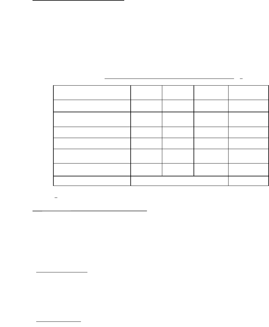
TABLE I. Physical property requirements of perfluorocarbon fluids
. 1/
Property Type I Type II Type III ASTM
test method
Boiling point (°C)
50-95 140-200 50-110 D-1120
Surface tension (Dynes/cm)
at 25°C
< 20
D-971
D-1331
Density at 25°C (gm/ml)
> 1.6 > 1.6 > 1.6 D-941
Density at 125°C (gm/ml)
> 1.5
D-941
Dielectric strength
(volts/mil)
> 300 > 300 > 300 877
Residue (:gm/gm) < 50 < 50 < 50 D-2109
Appearance Clear colorless NA
1
/ Perfluorocarbons contain no chlorine or hydrogen.
2.6 Test conditions C
4
and C
5
- optical gross/fine leak. This test condition applies to individual devices and devices
mounted on printed circuit boards or higher level assemblies. Apparatus required shall consist of suitable pressure or
vacuum/pressure chamber with an integral interferometry leak detector. The optical leak detector shall be preset and
properly calibrated for an equivalent standard leak rate sensitivity sufficient to read measured Helium leak rates of 10
-5
atm-
cc/sec and greater for gross leak detection (C
4
), and 5 X 10
-9
atm-cc/sec and greater for fine leak detection (C
5
).
Note: Prior to performing optical gross/fine leak testing, the test designer will need to know what limits the DUT has.
Extreme pressure/vacuum may cause damage to some devices. The test designer will need to design the test
conditions around such limitations.
2.6.1 Apparatus initial setup
. The optical gross/fine leak test equipment requires system parameter normalization as
determined uniquely for each particular device under test. To accomplish this an initial device package set up and
calibration shall be performed using two or more package specimens with a known hermeticity of <5X10
-8
cc-atm/sec and a
known internal free volume. These device packages shall be of the same type and geometry as the packages to be tested.
These known good packages are tested in the system to calibrate the device stiffness values used in determining the device
leak sensitivity (see 3.6.2).
2.6.2 Process monitoring
. A group of “system check devices” with a known hermeticity of <5X10
-8
cc-atm/sec, maintained
by the test facility, shall be used for system operation verification at the beginning and end of each work shift. This check of
the system’s operation shall be completed using a minimum of two package specimens from the “system check devices”.
*
*
*
*