MIL- STD-883F 2004 TEST METHOD STANDARD MICROCIRCUITS.pdf - 第84页
MIL-STD-883F METHOD 1014.11 18 June 2004 4 3. PROCEDURE . Fine and gr oss l eak tes ts s hall be c onduct ed in acc ordance wi th the r equirement s and proc edures of the spec ifi ed test condit ion. Tes ting or der sha…
MIL-STD-883F
METHOD 1014.11
18 June 2004
3
2.5 Test condition E, weight gain gross leak
. Apparatus for this test shall consist of:
a. A vacuum/pressure chamber for the evacuation and subsequent pressure bombing of devices up to 90 psia up to
10 hours.
b. An analytical balance capable of weighing the devices accurately to 0.1 milligram.
c. A source of type III detector fluid as specified in table I.
d. A filtration system capable of removing particles greater than 1 micrometer in size from the perfluorocarbon fluid.
e. Suitable calibrated instruments to measure test pressures and times.
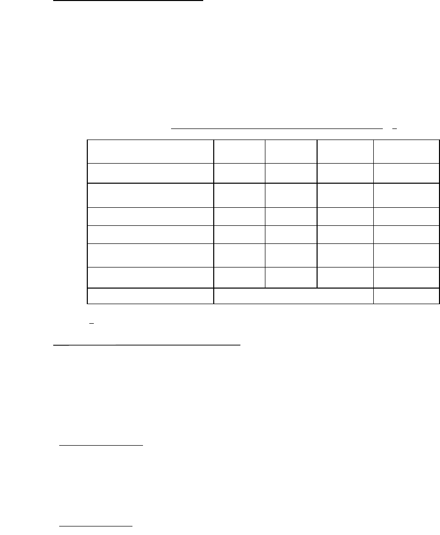
TABLE I. Physical property requirements of perfluorocarbon fluids
. 1/
Property Type I Type II Type III ASTM
test method
Boiling point (°C)
50-95 140-200 50-110 D-1120
Surface tension (Dynes/cm)
at 25°C
< 20
D-971
D-1331
Density at 25°C (gm/ml)
> 1.6 > 1.6 > 1.6 D-941
Density at 125°C (gm/ml)
> 1.5
D-941
Dielectric strength
(volts/mil)
> 300 > 300 > 300 877
Residue (:gm/gm) < 50 < 50 < 50 D-2109
Appearance Clear colorless NA
1
/ Perfluorocarbons contain no chlorine or hydrogen.
2.6 Test conditions C
4
and C
5
- optical gross/fine leak. This test condition applies to individual devices and devices
mounted on printed circuit boards or higher level assemblies. Apparatus required shall consist of suitable pressure or
vacuum/pressure chamber with an integral interferometry leak detector. The optical leak detector shall be preset and
properly calibrated for an equivalent standard leak rate sensitivity sufficient to read measured Helium leak rates of 10
-5
atm-
cc/sec and greater for gross leak detection (C
4
), and 5 X 10
-9
atm-cc/sec and greater for fine leak detection (C
5
).
Note: Prior to performing optical gross/fine leak testing, the test designer will need to know what limits the DUT has.
Extreme pressure/vacuum may cause damage to some devices. The test designer will need to design the test
conditions around such limitations.
2.6.1 Apparatus initial setup
. The optical gross/fine leak test equipment requires system parameter normalization as
determined uniquely for each particular device under test. To accomplish this an initial device package set up and
calibration shall be performed using two or more package specimens with a known hermeticity of <5X10
-8
cc-atm/sec and a
known internal free volume. These device packages shall be of the same type and geometry as the packages to be tested.
These known good packages are tested in the system to calibrate the device stiffness values used in determining the device
leak sensitivity (see 3.6.2).
2.6.2 Process monitoring
. A group of “system check devices” with a known hermeticity of <5X10
-8
cc-atm/sec, maintained
by the test facility, shall be used for system operation verification at the beginning and end of each work shift. This check of
the system’s operation shall be completed using a minimum of two package specimens from the “system check devices”.
*
*
*
*

MIL-STD-883F
METHOD 1014.11
18 June 2004
4
3. PROCEDURE
. Fine and gross leak tests shall be conducted in accordance with the requirements and procedures of
the specified test condition. Testing order shall be fine leak (condition A or B or C
5
) followed by gross leak (condition C
1
, C
3
,
C
4
, D, or E) except when C
4
is used together with A, B, or C
5
. When specified (see 4), measurements after test shall be
conducted following the leak test procedures. Where bomb pressure specified exceeds the microcircuit package capability,
alternate pressure, exposure time, and dwell time conditions may be used provided they satisfy the leak rate, pressure, time
relationships which apply, and provided a minimum of 30 psia (2 atmospheres absolute) bomb pressure is applied in any
case or for condition C
4
, a minimum of 10 psi differential test pressure is applied in any case. When test condition A
4
is
used, gross leak testing is not required. However A
4
shall not be used in lieu of the required seal testing of lidded packages.
When batch testing (more than one device in the leak detector at one time) is used in performing test condition A or B and a
reject condition occurs it shall be noted as a batch failure. Each device may then be tested individually one time for
acceptance if all devices in the batch are retested within one hour after removal from the tracer gas pressurization chamber.
For condition B only, devices may be batch retested for acceptance providing all retesting is completed within one hour after
removal from the tracer gas pressurization chamber. For condition C
3
only, devices that are batch tested, and indicate a
reject condition, may be retested individually one time using the procedure of 3.3.3.1 herein, except that repressurization is
not required if the devices are immersed in detector fluid within 20 seconds after completion of the first test, and they remain
in the bath until retest. For conditions C
4
and C
5
only, the package must meet lid stiffness requirements defined in 3.6.1.
This includes devices that are conformal coated such as circuit board assemblies.
3.1 Test condition A
1
, A
2
, or A
4
tracer gas (He) fine leak. Test condition A
1
is a "fixed" method with specified conditions in
accordance with table II that will ensure the test sensitivity necessary to detect the required measured leak rate (R
1
) . Test
condition A
2
is a "flexible" method that allows the variance of test conditions in accordance with the formula of 3.1.1.2 to
detect the specified equivalent standard leak rate (L) at a predetermined leak rate (R
1
). Test condition A
4
is a method that
will detect the required measured leak rate (R
1
) of an unsealed package.
3.1.1 Test conditions A
1
and A
2
, procedure applicable to "fixed" and "flexible" methods. The completed device(s), shall be
placed in a sealed chamber which is then pressurized with a tracer gas of 100 +0, -5 percent helium for the required time
and pressure. The pressure shall then be relieved and each specimen transferred to another chamber or chambers which
are connected to the evacuating system and a mass-spectrometer-type leak detector. When the chamber(s) is evacuated,
any tracer gas which was previously forced into the specimen will thus be drawn out and indicated by the leak detector as a
measured leak rate (R
1
). (The number of devices removed from pressurization for leak testing shall be limited such that the
test of the last device can be completed within 60 minutes for test condition A
1
or within the chosen value of dwell time t
2
for
test condition A
2
.)
Note: Flexible Method shall be used unless otherwise specified in the acquisition document, purchase order, or contract.
3.1.1.1 Test condition A
1
, fixed method. The devices(s) shall be tested using the appropriate conditions specified in table
II for the internal cavity volume of the package under test. The time t
1
is the time under pressure and time t
2
is the maximum
time allowed after release of pressure before the device shall be read. The fixed method shall not be used if the maximum
equivalent standard leak rate limit given in the acquisition document is less than the limits specified herein for the flexible
method.
*
*
MIL-STD-883F
METHOD 1014.11
18 June 2004
5
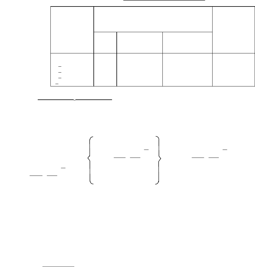
TABLE II. Fixed conditions for test condition A
1
.
Volume of
package (V)
in cm
3
Bomb condition
R
1
Reject limit
(atm cc/s He)
Psia
±2
Minimum
exposure time
hours (t
1
)
Maximum dwell
hours (t
2
)
<0.05
>
0.05 - <0.5
>
0.5 - <1.0
>
1.0 - <10.0
>
10.0 - <20.0
75
75
45
45
45
2
4
2
5
10
1
1
1
1
1
5 x 10
-8
5 x 10
-8
1 x 10
-7
5 x 10
-8
5 x 10
-8
3.1.1.2 Test condition A
2
, flexible method. Values for bomb pressure exposure time, and dwell time shall be chosen such
that actual measured tracer gas leak rate (R
1
) readings obtained for the devices under test (if defective) will be greater than
the minimum detection sensitivity capability of the mass spectrometer. The devices shall be subjected to a minimum of 2
atmospheres absolute of helium atmosphere. The chosen values, in conjunction with the value of the internal volume of the
device package to be tested and the maximum equivalent standard leak rate (L) limit (as shown below or as specified in the
applicable acquisition document), shall be used to calculate the measured leak rate (R
1
) limit using the following formula:
R
LP
P
M
M
e
LT
VP
M
M
e
LT
VP
M
M
E
O
A
AA
1
1
0
2
0
1
2
1
1
2
1
2
=
⎛
⎝
⎜
⎞
⎠
⎟ −
−
⎛
⎝
⎜
⎞
⎠
⎟
⎡
⎣
⎢
⎢
⎢
⎢
⎤
⎦
⎥
⎥
⎥
⎥
−
⎛
⎝
⎜
⎞
⎠
⎟
⎡
⎣
⎢
⎢
⎢
⎢
⎤
⎦
⎥
⎥
⎥
⎥
Where:
R
1
= The measured leak rate of tracer gas (He) through the leak in atm cc/s He.
L = The equivalent standard leak rate in atm cc/s air.
P
E
= The pressure of exposure in atmospheres absolute.
P
O
= The atmospheric pressure in atmospheres absolute. (1)
M
A
= The molecular weight of air in grams. (28.7)
M = The molecular weight of the tracer gas (Helium) in grams. (4)
t
1
= The time of exposure to P
E
in seconds.
t
2
= The dwell time between release of pressure and leak detection, in seconds.
V = The internal volume of the device package cavity in cubic centimeters.
3.1.1.2.1 Failure criteria
. Unless otherwise specified, devices with an internal cavity volume of 0.01 cc or less shall be
rejected if the equivalent standard leak rate (L) exceeds 5 x 10
-8
atm cc/s air. Devices with an internal cavity volume greater
than 0.01 cc and equal to or less than 0.4 cc shall be rejected if the equivalent standard leak rate (L) exceeds 1 x 10
-7
atm
cc/s air. Devices with an internal cavity volume greater than 0.4 cc shall be rejected if the equivalent standard leak rate (L)
exceeds 1 x 10
-6
atm cc/s air.
*