MIL- STD-883F 2004 TEST METHOD STANDARD MICROCIRCUITS.pdf - 第87页
MIL-STD-883F METHOD 1014.11 18 June 2004 7 3.2.2 Det erminat ion of c ounting ef fic iency ( k) . The count ing eff icienc y (k ) of equat ion (1) shall be det ermined as foll ows: a. Five repr esentat ive unit s of t he…

MIL-STD-883F
METHOD 1014.11
18 June 2004
6
3.1.2 Test condition A
4
, procedure applicable to the unsealed package method. The fixture and fittings of 2.1a. shall be
mounted to the evacuation port of the leak detector. Proof of fixturing integrity shall be verified by sealing a flat surfaced
metal plate utilizing the gasket of 2.1 (and grease or fluid of 2.1 if required to obtain seal) and measuring the response of the
leak test system. Testing shall be performed by sealing the package(s) to the evacuation port and the package cavity
evacuated to 0.1 torr or less. Care shall be taken to prevent contact of grease with package (seal ring not included) to avoid
masking leaks. The external portion of the package shall be flooded with Helium gas either by the use of an envelope or a
spray gun, at a pressure of 10 psig.
3.1.2.1 Failure criteria
. Unless otherwise specified, devices shall be rejected if the measured leak rate (R
1
) exceeds 1 x
10
-8
atm cc/s He.
3.2 Test condition B, radioisotope fine leak test
.
3.2.1 Activation parameters
. The activation pressure and soak time shall be determined in accordance with the following
equation:
Q
R
s
kT
Pt
S
= ()1
The parameters of equation (1) are defined as follows:
Q
S
= The maximum leak rate allowable, in atm cc/s Kr, for the devices to be tested.
R = Counts per minute above the ambient background after activation if the device leak rate were exactly equal
to Q
S
. This is the reject count above the background of both the counting equipment and the component, if
it has been through prior radioactive leak tests.
s = The specific activity, in microcuries per atmosphere cubic centimeter, of the krypton-85 tracer gas in the
activation system.
k = The overall counting efficiency of the scintillation crystal in counts per minute per microcurie of krypton-85 in
the internal void of the specific component being evaluated. This factor depends upon component
configuration and dimensions of the scintillation crystal. The counting efficiency shall be determined in
accordance with 3.2.2.
T = Soak time, in hours, that the devices are to be activated.
P = P
e
2
-P
i
2
, where P
e
is the activation pressure in atmospheres absolute and P
i
is the original internal pressure
of the devices in atmospheres absolute. The activation pressure (P
e
) may be established by specification or
if a convenient soak time (T) has been established, the activation pressure (P
e
) can be adjusted to satisfy
equation (1).
t = Conversion of hours to seconds and is equal to 3,600 seconds per hour.
NOTE: The complete version of equation (1) contains a factor (P
O
2
- ( ∆P)
2
) in the numerator which is a correction factor for
elevation above sea level. P
O
is sea level pressure in atmospheres absolute and ∆P is the difference in
pressure, in atmospheres between the actual pressure at the test station and sea level pressure. For the purpose
of this test method, this factor has been dropped.

MIL-STD-883F
METHOD 1014.11
18 June 2004
7
3.2.2 Determination of counting efficiency (k)
. The counting efficiency (k) of equation (1) shall be determined as follows:
a. Five representative units of the device type being tested shall be tubulated and the internal void of the device shall
be backfilled through the tubulation with a known volume and known specific activity of krypton-85 tracer gas and
the tubulation shall be sealed off.
b. The counts per minute shall be directly read in the shielded scintillation crystal of the counting station in which the
devices are read. From this value, the counting efficiency, in counts per minute per microcurie, shall be calculated.
3.2.3 Evaluation of surface sorption
. All device encapsulations consisting of glass, metal, and ceramic or combinations
thereof, including coatings and external sealants, shall be evaluated for surface sorption of krypton-85 before establishing
the leak test parameters. Representative samples of the questionable material shall be subjected to the predetermined
pressure and time conditions established for the device configuration as specified by 3.2.1. The samples shall then be
counted every 10 minutes, with count rates noted, until the count rate becomes asymptotic with time. (This is the point in
time at which surface sorption is no longer a problem.) This time lapse shall be noted and shall determine the "wait time"
specified in 3.2.4.
3.2.4 Procedure
. The devices shall be placed in radioactive tracer gas activation tank. The activation chamber may be
partially filled with inert material to reduce pumpdown time. The tank shall be evacuated to 0.5 torr. The devices shall be
subjected to a minimum of 2 atmospheres absolute pressure of krypton-85/dry nitrogen mixture for a minimum of 12
minutes. Actual pressure and soak time shall be determined in accordance with 3.2.1. The R value in counts per minute
shall not be less than 600 above background. The krypton-85/dry nitrogen gas mixture shall be evacuated to storage until
0.5 to 2.0 torr pressure exists in the activation tank. The storage cycle shall be completed in 3 minutes maximum as
measured from the end of the activation cycle or from the time the activation tank pressure reaches 60 psia if a higher
bombing pressure is used. The activation tank shall then immediately be backfilled with air (air wash). The devices shall
then be removed from the activation tank and leak tested within 1 hour after gas exposure with a
scintillation-crystal-equipped counting station. Device encapsulations that come under the requirements of 3.2.3 shall be
exposed to ambient air for a time not less than the "wait time" determined by 3.2.3. In no case will the time between removal
from the activation chamber and test exceed 1 hour. This exposure shall be performed after gas exposure but before
determining leak rate with the counting station. Device encapsulations that do not come under the requirements of 3.2.3 may
be tested without a "wait time." (The number of devices removed from pressurization for leak testing shall be limited such
that the test of the last device can be completed within 1 hour.) The actual leak rate of the component shall be calculated
with the following equation:
(ACTUAL READOUT IN NET COUNTS PER MINUTE) X Q
S
Q =
R
Where Q = Actual leak rate in atm cc/s, and QS and R are defined in 3.2.1.
NOTE: CAUTION. Discharge of krypton 85 into the atmosphere must not exceed limits imposed by local and Federal
regulations.
3.2.5 Failure criteria
. Unless otherwise specified, devices that exhibit a leak rate equal or greater than the test limits of
table III shall be considered as failures.
NOTE: CAUTION. Devices which do not exhibit a leak rate sufficient to fail seal test, may retain radioactive tracer gas in
sufficient concentration to cause soft errors in complex, small geometry devices.
MIL-STD-883F
METHOD 1014.11
18 June 2004
8
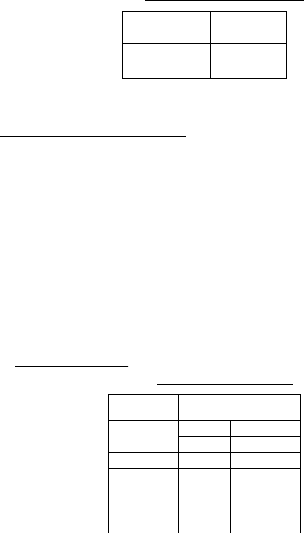
TABLE III. Test limits for radioisotope fine leak method
.
Volume of Q
S
package
cc
< 0.01 1 x 10
-8
> 0.01, < 0.4 5 x 10
-8
> 0.4 5 x 10
-7
3.2.6 Personnel precautions
. Federal, some state and local governmental regulations require a license for the
possession and use of krypton-85 leak test equipment. In the use of radioactive gas, these regulations and their maximum
permissible exposure and tolerance levels prescribed by law should be observed.
3.3 Test condition C
1
or C
3
, perfluorocarbon gross leak. Test condition C
1
is a fixed method with specified conditions that
will ensure the test sensitivity necessary. Test condition C
2
has been replaced by C
1
. Test condition C3 is a fixed method
that uses a vapor detection system instead of an indicator bath.
3.3.1 Procedure applicable to fixed (C
1
) method. The devices shall be placed in a vacuum/pressure chamber and the
pressure reduced to 5 torr or less and maintained for 30 minutes minimum. The vacuum cycle may be omitted for packages
with an internal volume >
0.1 cm
3
. A sufficient amount of type I detector fluid shall be admitted to cover the devices. When
the vacuum cycle is performed, the fluid will be admitted after the minimum 30 minute period but before breaking the
vacuum. The devices shall then be pressurized in accordance with table IV. When the pressurization period is complete
the pressure shall be released and the devices removed from the chamber without being removed from a bath of detector
fluid for greater than 20 seconds. A holding bath may be another vessel or storage tank. When the devices are removed
from the bath they shall be dried for 2 ±1 minutes in air prior to immersion in type II indicator fluid, which shall be maintained
at 125°C ±5°C. The devices shall be immersed with the uppermost portion at a minimum depth of 2 inches below the
surface of the indicator fluid, one at a time or in such a configuration that a single bubble from a single device out of a group
under observation may be clearly observed as to its occurrence and source. The device shall be observed against a dull,
nonreflective black background though the magnifier, while illuminated by the lighting source, from the instant of immersion
until, expiration of a 30-second minimum observation period, unless rejected earlier.
For packages greater than 5 grams, the effects of package thermal mass shall be determined by evaluating each package
family with known leakers and measuring the time for bubbles to be observed. If the evaluation time exceeds the 30
seconds required for the observation time, then the observation time shall be extended to take into account the package
thermal mass effect. Alternate methods may be used to meet this intent provided the method is documented and made
available to the preparing or acquiring activity upon request.
3.3.1.1 Test condition C
1
, fixed method. Allowable fixed method conditions shall be as shown in table IV, herein.
TABLE IV. Condition C pressurization conditions
.
Pressure
psia (min)
Minimum pressurization
time (hour)
C
1
C
3
30 23.5 12
45 8 4
60 4 2
75 2 1
90 1 0.5
105 0.5 N/A