MIL- STD-883F 2004 TEST METHOD STANDARD MICROCIRCUITS.pdf - 第90页
MIL-STD-883F METHOD 1014.11 18 June 2004 10 3.3. 4 Precaut ions . The fol lowing prec autions shal l be obser ved in conduc ting t he perfl uorocar bon gross leak t est: a. Perfluor ocarbon f luids shall be filt ered thr…
MIL-STD-883F
METHOD 1014.11
18 June 2004
9
3.3.2 Failure criteria
. A definite stream of bubbles or two or more large bubbles originating from the same point shall
be cause for rejection.
CAUTION: When the leak is large, the operator may notice a stream of liquid exiting the package without the release of
bubbles. This condition shall result in the package being rejected.
3.3.3 Test condition C
3
, perfluorocarbon vapor detection.
3.3.3.1 Procedure
. The devices shall be placed in a vacuum/pressure chamber and the pressure reduced to 5 torr and
maintained for 30 minutes minimum. A sufficient amount of type I detector fluid shall be admitted to the pressure chamber
to cover the devices. The fluid shall be admitted after the 30 minute minimum vacuum period but before breaking the
vacuum. The devices shall then be pressurized in accordance with table IV. The pressure shall be maintained for a period
of 30 minutes minimum. Upon completion of the pressurization period, the pressure shall be released, the devices removed
from the pressure chamber without being removed from a bath of detector fluid for more than 20 seconds and then retained
in a bath of perfluorocarbon fluid. When the devices are removed from the fluid they shall be air dried for a minimum of 20
seconds and a maximum of 5 minutes prior to the test cycle. If the type I detector fluid has a boiling point of less than 80°C,
the maximum drying time shall be 3 minutes.
The devices shall then be tested with a perfluorocarbon vapor detector that is calibrated in accordance with 2.3h and 2.3i.
"Purge" time shall be in accordance with table V. Test time shall be a minimum of 3.5 seconds (unless the device is rejected
earlier) with the perfluorocarbon vapor detector purge and test chambers at a temperature of 125 ±5°C, or 2.5 seconds
minimum with the purge and test chambers at a temperature of 150 ±5°C.
NOTE: Air dry, purge and test limits for each device shall be complied with in all cases, including stick to stick handling.
NOTE: Test temperature shall be measured at the chamber surface that is in contact with the device(s) being tested.
Device orientation within the test cell should maximize heat transfer from the heated chamber surface to the cavity
of the device within the capability of the equipment.
3.3.3.2 Failure criteria
. A device shall be rejected if the detector instrumentation indicates more than the equivalent of
0.167 or 1/6 microliter of type I detector fluid in accordance with table I.
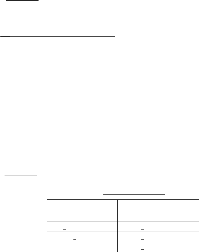
TABLE V. Purge time for condition C
3
.
Package with internal Purge time
free volume
(CM
3
) (seconds)
<0.01 < 5
>0.01 <0.10 < 9
>0.10 < 13
NOTE: Maximum purge time can be determined by cycling a device with a 0.02 to 0.05 inch hole and measuring the
maximum purge time that can be used without permitting the device to escape detection during the test cycle.
MIL-STD-883F
METHOD 1014.11
18 June 2004
10
3.3.4 Precautions
. The following precautions shall be observed in conducting the perfluorocarbon gross leak test:
a. Perfluorocarbon fluids shall be filtered through a filter system capable of removing particles greater than 1
micrometer prior to use. Bulk filtering and storage is permissible. Liquid which has accumulated observable
quantities of particulate matter during use shall be discarded or reclaimed by filtration for re-use. Precaution should
be taken to prevent contamination.
b. Observation container shall be filled to assure coverage of the device to a minimum of 2 inches.
c. Devices to be tested should be free from foreign materials on the surface, including conformal coatings and any
markings which may contribute to erroneous test results.
d. A lighting source capable of producing at least 15 thousand foot candles in air at a distance equal to that which the
most distant device in the bath will be from the source. The lighting source shall not require calibration but the light
level at the point of observation (i.e., where the device under test is located during observation for bubbles) shall
be verified.
e. Precaution should be taken to prevent operator injury due to package rupture or violent evolution of bomb fluid
when testing large packages.
3.4 Test condition D, penetrant dye gross leak
. This test shall be permitted only for destructive verification of devices
(see 3.7). The pressure chamber shall be filled with the dye solution to a depth sufficient to completely cover all the devices.
The devices shall be placed in the solution and the chamber pressurized at 105 psia minimum for 3 hours minimum. For
device packages which will not withstand 105 psia, 60 psia minimum for 10 hours may be used. The devices shall then be
removed and carefully washed, using a suitable solvent for the dye used, followed by an air-jet dry. The devices shall then
be immediately examined under the magnifier using an ultraviolet light source of appropriate frequency.
3.4.1 Failure criteria
. Any evidence of dye penetration into the device cavity shall constitute a failure.
3.5 Test condition E, weight gain gross leak
.
3.5.1 Procedure
. The devices shall be placed in an oven at 125°C for 1 hour minimum, after which they shall be allowed
to cool to room ambient temperature. Each device shall be weighed and the initial weight recorded or the devices may be
categorized into cells as follows. Devices having a volume of <0.01 cc shall be categorized in cells of 0.5 milligram
increments and devices with volume >
0.01 cc shall be categorized in cells of 1.0 milligram increments. The devices shall be
placed in a vacuum/pressure chamber and the pressure reduced to 5 torr and maintained for 1 hour except that for devices
with an internal cavity volume >
0.1 cc, this vacuum cycle may be omitted. A sufficient amount of type III detector fluid shall
be admitted to the pressure chamber to cover the devices. When the vacuum cycle is performed, the fluid shall be admitted
after the 1-hour period but before breaking the vacuum. The devices shall then be pressurized to 75 psia minimum except
that 90 minimum psia shall be used when the vacuum cycle has been omitted. The pressure shall be maintained for 2 hours
minimum. If the devices will not withstand the 75 psia test pressure, the pressure may be lowered to 45 psia minimum with
the vacuum cycle and the pressure maintained for 10 hours minimum.
Upon completion of the pressurization period, the pressure shall be released and the devices removed from the pressure
chamber and retained in a bath of the perfluorocarbon fluid. When the devices are removed from the fluid they shall be air
dried for 2 ±1 minutes prior to weighing. Transfer the devices singly to the balance and determine the weight or weight
category of each device. All devices shall be tested within 4 minutes following removal from the fluid. The delta weight shall
be calculated from the record of the initial weight and the post weight of the device. Devices which were categorized shall
be separated into two groups, one group which shall be devices which shifted one cell or less and the other group which
shall be devices which shifted more than one cell.

MIL-STD-883F
METHOD 1014.11
18 June 2004
11
3.5.2 Failure criteria
. A device shall be rejected if it gains 1.0 milligram or more and has an internal volume of < 0.01 cm
3
and 2.0 milligrams or more if the volume is > 0.01 cm
3
. If the devices are categorized, any device which gains enough
weight to cause it to shift by more than one cell shall be considered a reject. A device which loses weight of an amount
which if gained would cause the device to be rejected may be retested after it is baked at 125°C for a period of 8 hours.
3.6 Test condition C
4
or C
5
- optical gross/fine leak.
3.6.1 Lid Stiffness
. Test condition C
4
and C
5
are valid for packages with relatively thin metallic or ceramic lids or other
materials that meet the lid stiffness requirements stated below. The test sensitivity is related to the extent of measurable
deformation of the lid. The measurable deformation is increased by increasing the specific pressure differential and the test
time used. For a specific lid material and size the following formula indicates the minimum measurable deformation:
For condition C
4
:
R
4
/ET
3
> 1.0 X 10
-4
For condition C
5
:
R
4
/ET
3
> 3.0 X 10
-4
Where:
R = The minimum width of free lid (inside braze or cavity dimension in inches).
E = The modulus of elasticity of the lid material.
For Example: E= 10 X 10
6
lbs/in
2
for Aluminum,
E = 20 X 10
6
lbs/in
2
for Kovar,
and E = 60 X 10
6
lbs/in
2
for Ceramic.
T = The thickness of the lid (inches).
Note: As test time (t) and pressure (P
0
) are increased, C
5
will become smaller approaching C
4
.
*
*
*