MIL- STD-883F 2004 TEST METHOD STANDARD MICROCIRCUITS.pdf - 第91页
MIL-STD-883F METHOD 1014.11 18 June 2004 11 3.5. 2 Failur e cri teri a . A devic e shall be reject ed if it gains 1. 0 mill igram or more and has an i nternal vol ume of < 0.01 c m 3 and 2.0 m illigrams or m ore if th…

MIL-STD-883F
METHOD 1014.11
18 June 2004
10
3.3.4 Precautions
. The following precautions shall be observed in conducting the perfluorocarbon gross leak test:
a. Perfluorocarbon fluids shall be filtered through a filter system capable of removing particles greater than 1
micrometer prior to use. Bulk filtering and storage is permissible. Liquid which has accumulated observable
quantities of particulate matter during use shall be discarded or reclaimed by filtration for re-use. Precaution should
be taken to prevent contamination.
b. Observation container shall be filled to assure coverage of the device to a minimum of 2 inches.
c. Devices to be tested should be free from foreign materials on the surface, including conformal coatings and any
markings which may contribute to erroneous test results.
d. A lighting source capable of producing at least 15 thousand foot candles in air at a distance equal to that which the
most distant device in the bath will be from the source. The lighting source shall not require calibration but the light
level at the point of observation (i.e., where the device under test is located during observation for bubbles) shall
be verified.
e. Precaution should be taken to prevent operator injury due to package rupture or violent evolution of bomb fluid
when testing large packages.
3.4 Test condition D, penetrant dye gross leak
. This test shall be permitted only for destructive verification of devices
(see 3.7). The pressure chamber shall be filled with the dye solution to a depth sufficient to completely cover all the devices.
The devices shall be placed in the solution and the chamber pressurized at 105 psia minimum for 3 hours minimum. For
device packages which will not withstand 105 psia, 60 psia minimum for 10 hours may be used. The devices shall then be
removed and carefully washed, using a suitable solvent for the dye used, followed by an air-jet dry. The devices shall then
be immediately examined under the magnifier using an ultraviolet light source of appropriate frequency.
3.4.1 Failure criteria
. Any evidence of dye penetration into the device cavity shall constitute a failure.
3.5 Test condition E, weight gain gross leak
.
3.5.1 Procedure
. The devices shall be placed in an oven at 125°C for 1 hour minimum, after which they shall be allowed
to cool to room ambient temperature. Each device shall be weighed and the initial weight recorded or the devices may be
categorized into cells as follows. Devices having a volume of <0.01 cc shall be categorized in cells of 0.5 milligram
increments and devices with volume >
0.01 cc shall be categorized in cells of 1.0 milligram increments. The devices shall be
placed in a vacuum/pressure chamber and the pressure reduced to 5 torr and maintained for 1 hour except that for devices
with an internal cavity volume >
0.1 cc, this vacuum cycle may be omitted. A sufficient amount of type III detector fluid shall
be admitted to the pressure chamber to cover the devices. When the vacuum cycle is performed, the fluid shall be admitted
after the 1-hour period but before breaking the vacuum. The devices shall then be pressurized to 75 psia minimum except
that 90 minimum psia shall be used when the vacuum cycle has been omitted. The pressure shall be maintained for 2 hours
minimum. If the devices will not withstand the 75 psia test pressure, the pressure may be lowered to 45 psia minimum with
the vacuum cycle and the pressure maintained for 10 hours minimum.
Upon completion of the pressurization period, the pressure shall be released and the devices removed from the pressure
chamber and retained in a bath of the perfluorocarbon fluid. When the devices are removed from the fluid they shall be air
dried for 2 ±1 minutes prior to weighing. Transfer the devices singly to the balance and determine the weight or weight
category of each device. All devices shall be tested within 4 minutes following removal from the fluid. The delta weight shall
be calculated from the record of the initial weight and the post weight of the device. Devices which were categorized shall
be separated into two groups, one group which shall be devices which shifted one cell or less and the other group which
shall be devices which shifted more than one cell.

MIL-STD-883F
METHOD 1014.11
18 June 2004
11
3.5.2 Failure criteria
. A device shall be rejected if it gains 1.0 milligram or more and has an internal volume of < 0.01 cm
3
and 2.0 milligrams or more if the volume is > 0.01 cm
3
. If the devices are categorized, any device which gains enough
weight to cause it to shift by more than one cell shall be considered a reject. A device which loses weight of an amount
which if gained would cause the device to be rejected may be retested after it is baked at 125°C for a period of 8 hours.
3.6 Test condition C
4
or C
5
- optical gross/fine leak.
3.6.1 Lid Stiffness
. Test condition C
4
and C
5
are valid for packages with relatively thin metallic or ceramic lids or other
materials that meet the lid stiffness requirements stated below. The test sensitivity is related to the extent of measurable
deformation of the lid. The measurable deformation is increased by increasing the specific pressure differential and the test
time used. For a specific lid material and size the following formula indicates the minimum measurable deformation:
For condition C
4
:
R
4
/ET
3
> 1.0 X 10
-4
For condition C
5
:
R
4
/ET
3
> 3.0 X 10
-4
Where:
R = The minimum width of free lid (inside braze or cavity dimension in inches).
E = The modulus of elasticity of the lid material.
For Example: E= 10 X 10
6
lbs/in
2
for Aluminum,
E = 20 X 10
6
lbs/in
2
for Kovar,
and E = 60 X 10
6
lbs/in
2
for Ceramic.
T = The thickness of the lid (inches).
Note: As test time (t) and pressure (P
0
) are increased, C
5
will become smaller approaching C
4
.
*
*
*
MIL-STD-883F
METHOD 1014.11
18 June 2004
12
3.6.2 Leak sensitivity
. The optical leak test shall be performed with a test pressure (P
0
) and time (t), which will provide
the leak rate sensitivity required. The leak rate sensitivity is provided by the following equation:
L = (-V
0
/ k
2
t) X ln (1-d
yt
/P
0
L
0
)
Where:
L = The leak rate sensitivity of the test (atm-cc/sec).
V
0
= The volume of the package cavity (in
3
).
K
2
= The leak test gas constant (air = 1.0, He = 2.67)
t = The test duration time (seconds).
D
Yt
= The measured deformation of the package lid (inches).
P
0
= The chamber pressure during the test (psig).
L
0
= The lid stiffness constant calculated from the package dimensions (inch/psi).
Note: L
0
is calculated using the Roark formula for stress and strain on a flat plate having a uniform load over the
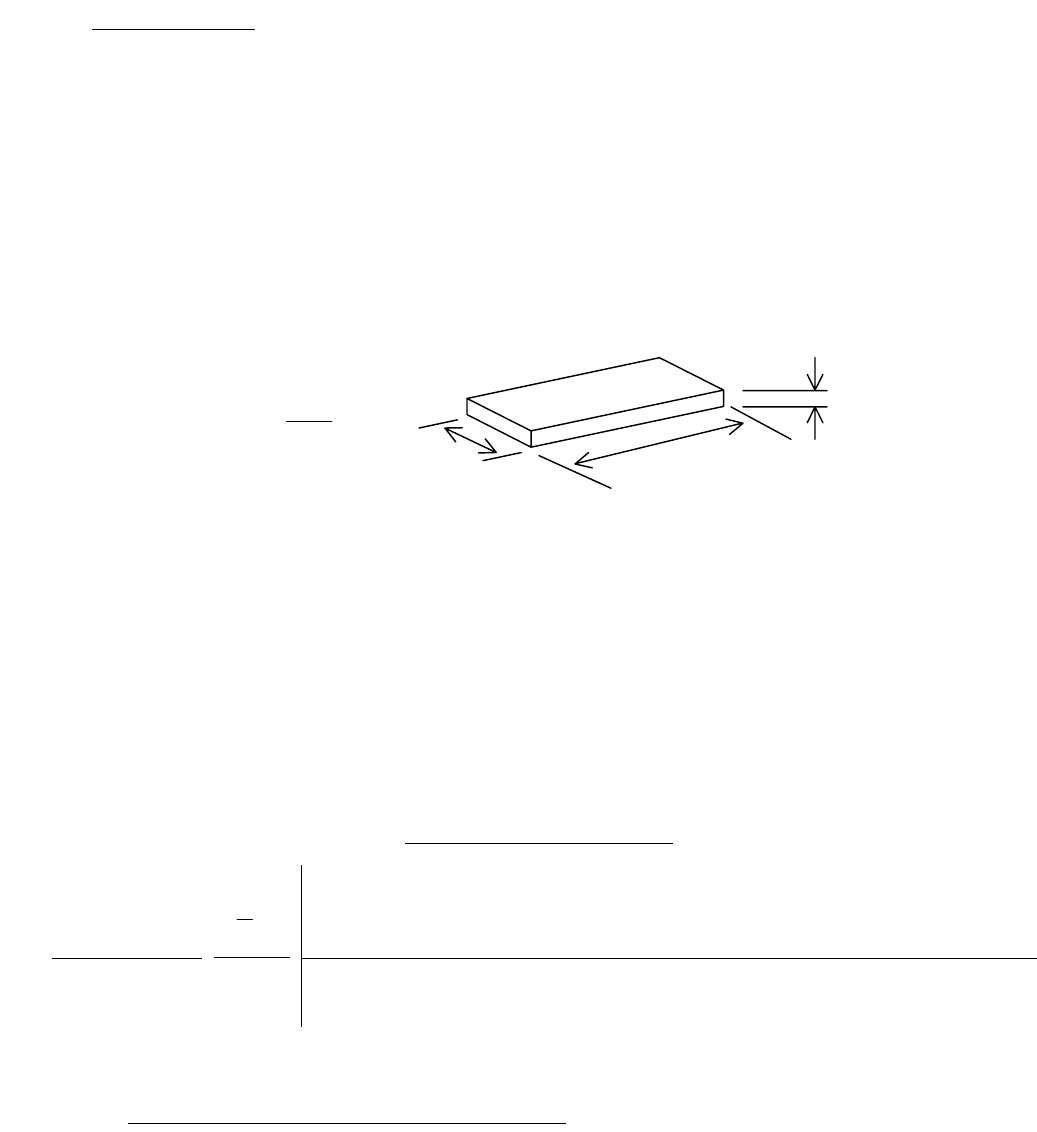
entire area. The formula for a rectangular lid is:
3
4
0
ET
b
L
α
=
Where:
α = Aspect Ratio Constant determined by measurements a and b (See table VI, below.)
a = Lid length – measure of the longer side (inches).
b = Lid width – measure of the shorter side (inches).
E = Modulus of Elasticity for the lid material used.
T = Lid thickness (inches).
The Aspect Ratio Constant (α) can be selected from a table based on the dimensions of the package lid and a
determination of which package model best describes the structure of the package. These models are respectively
based on “pin” or “fixed” boundary conditions.
Condition 1 (pin boundary): Flexible Wall Package (e.g. thin walled packages or stamped packages)
Condition 2 (fixed boundary): Rigid fixed wall package (e.g. thick walled or ceramic packages)
TableVI: Aspect Ratio Constant (α)
Aspect Ratio
1
1.2
1.4
1.6
1.8
2
3
4
5
∞
Flexible
Package α - pin 0.0444 0.0616 0.0770 0.0906 0.1017 0.1110 0.1335 0.1400 0.1417 0.1421
Rigid Package α - fixed 0.0138 0.0188 0.0226 0.0251 0.0267 0.0277 0.0284
These two package models represent the limits of the lid stiffness calculations. The stiffness of virtually all package lids will
lie within the limits set by the pin and fixed boundary conditions.
3.6.2.1 Controlling sensitivity by controlling test time and pressure
. As stated above, for a specific package lid thickness (T),
and volume (V
0
), the leak rate sensitivity (L) is improved by increasing the test time (t) and chamber pressure (P
0
).
*
*
b
T
a
b
a
*
*