MIL- STD-883F 2004 TEST METHOD STANDARD MICROCIRCUITS.pdf - 第92页
MIL-STD-883F METHOD 1014.11 18 June 2004 12 3.6.2 Leak sensi tivi ty . The opti cal l eak tes t shal l be perf ormed wit h a test press ure (P 0 ) and ti me (t), which wi ll pr ovide the leak rate s ensit ivit y requir e…

MIL-STD-883F
METHOD 1014.11
18 June 2004
11
3.5.2 Failure criteria
. A device shall be rejected if it gains 1.0 milligram or more and has an internal volume of < 0.01 cm
3
and 2.0 milligrams or more if the volume is > 0.01 cm
3
. If the devices are categorized, any device which gains enough
weight to cause it to shift by more than one cell shall be considered a reject. A device which loses weight of an amount
which if gained would cause the device to be rejected may be retested after it is baked at 125°C for a period of 8 hours.
3.6 Test condition C
4
or C
5
- optical gross/fine leak.
3.6.1 Lid Stiffness
. Test condition C
4
and C
5
are valid for packages with relatively thin metallic or ceramic lids or other
materials that meet the lid stiffness requirements stated below. The test sensitivity is related to the extent of measurable
deformation of the lid. The measurable deformation is increased by increasing the specific pressure differential and the test
time used. For a specific lid material and size the following formula indicates the minimum measurable deformation:
For condition C
4
:
R
4
/ET
3
> 1.0 X 10
-4
For condition C
5
:
R
4
/ET
3
> 3.0 X 10
-4
Where:
R = The minimum width of free lid (inside braze or cavity dimension in inches).
E = The modulus of elasticity of the lid material.
For Example: E= 10 X 10
6
lbs/in
2
for Aluminum,
E = 20 X 10
6
lbs/in
2
for Kovar,
and E = 60 X 10
6
lbs/in
2
for Ceramic.
T = The thickness of the lid (inches).
Note: As test time (t) and pressure (P
0
) are increased, C
5
will become smaller approaching C
4
.
*
*
*
MIL-STD-883F
METHOD 1014.11
18 June 2004
12
3.6.2 Leak sensitivity
. The optical leak test shall be performed with a test pressure (P
0
) and time (t), which will provide
the leak rate sensitivity required. The leak rate sensitivity is provided by the following equation:
L = (-V
0
/ k
2
t) X ln (1-d
yt
/P
0
L
0
)
Where:
L = The leak rate sensitivity of the test (atm-cc/sec).
V
0
= The volume of the package cavity (in
3
).
K
2
= The leak test gas constant (air = 1.0, He = 2.67)
t = The test duration time (seconds).
D
Yt
= The measured deformation of the package lid (inches).
P
0
= The chamber pressure during the test (psig).
L
0
= The lid stiffness constant calculated from the package dimensions (inch/psi).
Note: L
0
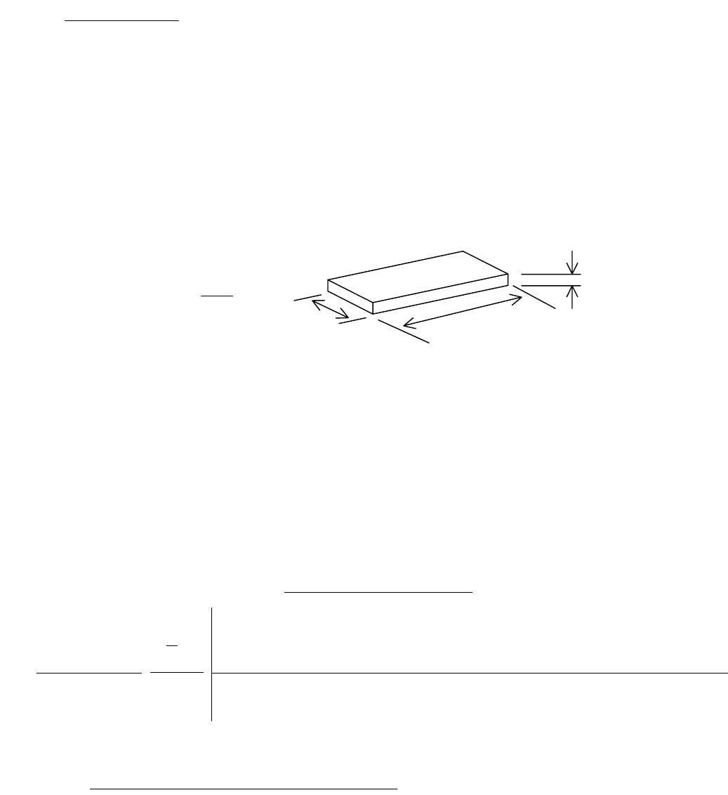
is calculated using the Roark formula for stress and strain on a flat plate having a uniform load over the
entire area. The formula for a rectangular lid is:
3
4
0
ET
b
L
α
=
Where:
α = Aspect Ratio Constant determined by measurements a and b (See table VI, below.)
a = Lid length – measure of the longer side (inches).
b = Lid width – measure of the shorter side (inches).
E = Modulus of Elasticity for the lid material used.
T = Lid thickness (inches).
The Aspect Ratio Constant (α) can be selected from a table based on the dimensions of the package lid and a
determination of which package model best describes the structure of the package. These models are respectively
based on “pin” or “fixed” boundary conditions.
Condition 1 (pin boundary): Flexible Wall Package (e.g. thin walled packages or stamped packages)
Condition 2 (fixed boundary): Rigid fixed wall package (e.g. thick walled or ceramic packages)
TableVI: Aspect Ratio Constant (α)
Aspect Ratio
1
1.2
1.4
1.6
1.8
2
3
4
5
∞
Flexible
Package α - pin 0.0444 0.0616 0.0770 0.0906 0.1017 0.1110 0.1335 0.1400 0.1417 0.1421
Rigid Package α - fixed 0.0138 0.0188 0.0226 0.0251 0.0267 0.0277 0.0284
These two package models represent the limits of the lid stiffness calculations. The stiffness of virtually all package lids will
lie within the limits set by the pin and fixed boundary conditions.
3.6.2.1 Controlling sensitivity by controlling test time and pressure
. As stated above, for a specific package lid thickness (T),
and volume (V
0
), the leak rate sensitivity (L) is improved by increasing the test time (t) and chamber pressure (P
0
).
*
*
b
T
a
b
a
*
*

MIL-STD-883F
METHOD 1014.11
18 June 2004
13
3.6.3 Test condition C
4
- optical gross leak. (This test may be performed in conjunction with optical fine leak C
5
.) The
completed device(s) shall be placed in the sealed test chamber. The optical interferometer shall be set to observe the
package lid(s). The chamber shall then be pressurized or evalcuated while the deformation of the lid(s) is being observed
with the optical interferometer. The deformation of the lid(s) with the pressure change, and the lack of continued
deformation of the lid(s) with the pressure (P
0
) held for time t (or equivalent procedure), will be observed for each package in
the field of view simultaneously.
3.6.3.1 Failure criteria.
A device shall be rejected for any of the following criteria:
a. If the optical interferometer did not detect deformation of the lid as the chamber pressure was changed.
b. If the interferometer detects the lid deforming as the chamber pressure is held constant (or equivalent procedure.
3.6.4 Test condition C
5
– optical fine leak . (This test may be performed in conjunction with optical gross leak C
4
.) The
completed device(s) shall be placed in the sealed test chamber. An optical interferometer is set to observe the package
lid(s). The sealed test chamber is then pressurized with Helium gas to no more than the maximum design pressure as
determined by the package manufacturer or the design limit of the chamber, which ever is less. The chamber is then
pressurized or evacuated while the deformation of the lid(s) is being measured with the optical interferometer. The
deformation of the lid(s) with the pressure change for time t (or equivalent procedure) will be measured for each package in
the field of view simultaneously.
The sealed test chamber is then pressurized with Helium gas to 30 psig. The lack of deflection of the lid(s) is then observed
with an optical interferometer for time t
2
(or equivalent procedure).
3.6.4.1 Failure criteria
. A device shall be rejected for any of the three following criteria:
a. If the interferometer did not detect proportional deformation of the lid as the chamber pressure was charged.
b. If the interferometer detects the lid deforming from the package leaking in the pressurized Helium gas during time t
as the pressure is held constant (or equivalent procedure).
3.7 Retest
. Devices which fail gross leak (test conditions C or E) may be retested destructively. If the retest shows a
device to pass, that was originally thought to be a failure, then the device need not be counted as a failure in the accept
number of sample size number calculations. Devices which fail fine leak (test conditions A
1
, A
2
, A
4
, or B) shall not be
retested for acceptance unless specifically permitted by the applicable acquisition document. Where fine leak retest is
permitted, the entire leak test procedure for the specified test condition shall be repeated. That is, retest consisting of a
second observation on leak detection without a re-exposure to the tracer fluid or gas under the specified test condition shall
not be permissible under any circumstances. Preliminary measurement to detect residual tracer gas is advisable before any
retest.
4. SUMMARY
. The following details shall be specified in the applicable acquisition document:
a. Test condition letter when a specific test is to be applied (see 3).
b. Accept or reject leak rate for test condition A or B or C
5
when other than the accept or reject leak rate specified
herein applies (see 3.1.1.1, 3.1.1.2, 3.1.2, 3.2.5, and 3.6.4.1).
c. Where applicable, measurements after test (see 3).
d. Retest acceptability for test conditions A and B (see 3.7).
e. Order of performance of fine and gross if other than fine followed by gross except when using C
4
/C
5
(see 3).
f. Where applicable, the device package pressure rating shall be specified if that rating is less than 75 psia.
g. Leak testing with conditions C
4
and C
5
also includes package testing on completed assemblies (PC boards),
packages with external absorbing materials (connectors), or other special conditions.
*
*
*
*
*
*
*
*
*
*
*
*