MIL- STD-883F 2004 TEST METHOD STANDARD MICROCIRCUITS.pdf - 第97页
MIL-STD-883F METHOD 1015.9 1 June 1993 3 3.2.2 Cool down after ac cel erated bur n-in . All devices subject ed to the ac celer ated tes ting of condit ion F shal l be cool ed to withi n 10°C of power s table at room temp…

MIL-STD-883F
METHOD 1015.9
1 June 1993
2
3.1.1.1 Test temperature for high power devices. Regardless of power level, devices shall be able to be burned in or
life-tested at their maximum rated operating temperature. For devices whose maximum operating temperature is stated in
terms of ambient temperature, T
A
, table I applies. For devices whose maximum operating temperature is stated in terms of
case temperature, T
C
and where the ambient temperature would cause T
J
to exceed +200°C (+175°C for class level S), the
ambient operating temperature may be reduced during burn-in and life test from +125°C to a value that will demonstrate a T
J
between +175°C and +200°C and T
C
equal to or greater than +125°C without changing the test duration. Data supporting
this reduction shall be available to the acquiring and qualifying activities upon request.
3.1.1.2 Test temperature for hybrid devices
. The ambient or case burn-in test temperature shall be as specified in table I,
except case temperature burn-in shall be performed, as a minimum, at the maximum operating case temperature (T
C
)
specified for the device. Burn-in shall be 320 hours minimum for class level S hybrids (class K). The device should be
burned in at the maximum specified operating temperature, voltage, and loading conditions as specified in the device
specification or drawing. Since case and junction temperature will, under normal circumstances, be significantly higher than
ambient temperature, the circuit should be so structured that the maximum rated junction temperature as specified in the
device specification or drawing, and the cure temperature of polymeric materials as specified in the baseline documentation
shall not be exceeded. If no maximum junction temperature is specified, a maximum of 175°C is assumed. Accelerated
burn-in (condition F) shall not be permitted. The specified test temperature shall be the minimum actual ambient or case
temperature that must be maintained for all devices in the chamber. This shall be assured by making whatever adjustments
are necessary in the chamber profile, loading, location of control or monitoring instruments and the flow of air or other
suitable gas or liquid chamber medium.
3.1.2 Temperature accelerated test details
. In test condition F, microcircuits are subjected to bias(es) at a temperature
(175°C to 250°C) which considerably exceeds the maximum rated junction temperature. At these elevated temperatures, it
is generally found that microcircuits will not operate normally as specified in their applicable acquisition documents, and it is
therefore necessary that special attention be given to the choice of bias circuits and conditions to assure that important
circuit areas are adequately biased without subjecting other areas of the circuit to damaging overstress(es). To properly
select the accelerated test conditions, it is recommended that an adequate sample of devices be exposed to the intended
high temperature while measuring voltage(s) and current(s) at each device terminal to assure that the applied electrical
stresses do not induce damaging overstress. Unless otherwise specified in the device specifications or drawings, the
minimum time-temperature combination shall be as delineated by table I. The minimum test time shall be 12 hours. The
applied voltage at any or all terminals shall be equal to the recommended operating voltage(s) at 125°C. When excessive
current flow or power dissipation would result from operation at the specified voltage(s), the applied voltage(s) at any or all
terminals may be reduced to a minimum of 50 percent of the specified voltage(s) and the testing time shall be determined in
accordance with the formula given in 3.5.6 of method 1005. Devices with internal thermal shut-down circuitry shall be
handled in accordance with 3.5.6.1 of method 1005. Thermal runaway conditions must be avoided at all times.
3.2 Measurements
. Pre burn-in measurements, when specified, or at the manufacturer's discretion when not specified,
shall be conducted prior to applying burn-in test conditions. Post burn-in measurements shall be completed within 96 hours
after removal of the devices from the specified burn-in test condition (i.e., either removal of temperature or bias) and shall
consist of all 25°C dc parameter measurements) (subgroup A-1 of method 5005, or subgroups tested in lieu of A-1 as
allowed in the most similar military device specification or standard microcircuit drawing) and all parameters for which delta
limits have been specified as part of interim (post-burn-in) electrical measurements. Delta limit acceptance, when
applicable, shall be based upon these measurements. If these measurements cannot be completed within 96 hours, for
either the standard or accelerated burn-in, the devices shall be subjected to the same test condition (see 3.1) and
temperature previously used for a minimum additional reburn-in time as specified in table I before post burn-in
measurements are made.
3.2.1 Cooldown after standard burn-in
. All devices shall be cooled to within 10°C of their power stable condition at room
temperature prior to the removal of bias. The interruption of bias for up to 1 minute for the purpose of moving the devices to
cooldown positions separate from the chamber within which burn-in testing was performed shall not be considered removal
of bias, (bias at cooldown position shall be same as that used during burn-in). Alternatively, except for linear or MOS
(CMOS, NMOS, PMOS, etc.) devices or unless otherwise specified, the bias may be removed during cooling provided the
case temperature of devices under test is reduced to a maximum of 35°C within 30 minutes after the removal of the test
conditions and provided the devices under test are removed from the heated chamber within 5 minutes following removal of
bias. All 25°C dc measurements or alternate subgroups (see 3.2) shall be completed prior to any reheating of the device(s).

MIL-STD-883F
METHOD 1015.9
1 June 1993
3
3.2.2 Cooldown after accelerated burn-in
. All devices subjected to the accelerated testing of condition F shall be cooled
to within 10°C of power stable at room temperature prior to the removal of bias. Interruption of bias for a period of up to 1
minute for the purpose of moving devices to cooldown positions separate from the chamber within which burn-in was
conducted shall not be considered removal of bias, (bias at cooldown position shall be same as that used during burn-in).
All specified 25°C dc electrical measurements shall be completed prior to any reheating of the devices.
3.2.3 Test setup monitoring
. The test setup shall be monitored at the test temperature initially and at the conclusion of
the test to establish that all devices are being stressed to the specified requirements. The following is the minimum
acceptable monitoring procedure:
a. Device sockets. Initially and at least each 6 months thereafter, (once every 6 months or just prior to use if not used
during the 6 month period) each test board or tray shall be checked to verify continuity to connector points to assure
that bias supplies and signal information will be applied to each socket. Board capacitance or resistance required to
ensure stability of devices under test shall be checked during these initial and periodic verification tests to ensure they
will perform their proper function (i.e., that they are not open or shorted). Except for this initial and periodic
verification, each device or device socket does not have to be checked; however, random sampling techniques shall
be applied prior to each time a board is used and shall be adequate to assure that there are correct and continuous
electrical connections to the devices under test.
b. Connectors to test boards or trays. After the test boards are loaded with devices, inserted into the oven, and brought
up to at least 125°C (or the specified test temperature, if less than 125°C) each required test voltage and signal
condition shall be verified in at least one location on each test board or tray so as to assure electrical continuity and
the correct application of specified electrical stresses for each connection or contact pair used in the applicable test
configuration. This shall be performed by opening the oven for a maximum of 10 minutes.
c. At the conclusion of the test period, prior to removal of devices from temperature and test conditions, the voltage and
signal condition verification of b above shall be repeated.
d. For class level S devices, each test board or tray and each test socket shall be verified prior to test to assure that the
specified test conditions are applied to each device. This may be accomplished by verifying the device functional
response at each device output(s). An approved alternate procedure may be used.
Where failures or open contacts occur which result in removal of the required test stresses for any period of the required test
duration (see 3.1), the test time shall be extended to assure actual exposure for the total minimum specified test duration.
Any loss(es) or interruption(s) of bias in excess of 10 minutes total duration while the chamber is at temperature during the
final 8 hours of burn-in shall require extension of the test duration for an uninterrupted 8 hours minimum, after the last bias
interruption.
4. SUMMARY
. The following details shall be specified in the applicable acquisition document:
a. Test duration if other than as defined for the applicable class level in method 5004, or time-temperature combination
shown in table I.
b. Test condition letter.
c. Burn-in test temperature, and whether ambient, junction, or case (see 3), if other than as specified in 3.1.1.
d. Test mounting, if other than normal (see 3).
e. Pre and post burn-in measurements and drift limits, as applicable (see 3.2).
f. Authorization for use of condition F and special maximum test rating for condition F (see 3.1 and 3.1.2), when
applicable.
g. Time within which post burn-in measurements must be completed if other than specified (see 3.2).
MIL-STD-883F
METHOD 1015.9
1 June 1993
4
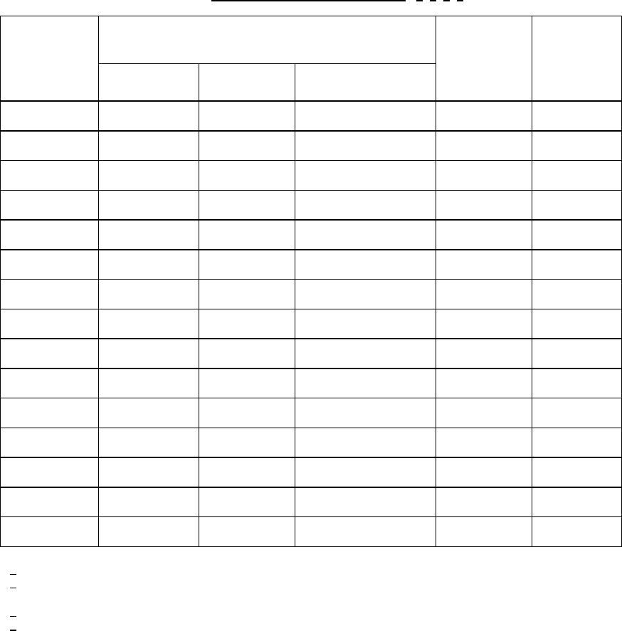
TABLE I. Burn-in time-temperature regression. 1/ 2/ 3/ 4/
Minimum
temperature
T
A
(°C)
Minimum time (hours) Test
condition
(see 3.1)
Minimum
reburn-in
time (hours)
Class level S Class level B Class level S hybrids
(Class K)
100 --- 352 700 Hybrids only 24
105 --- 300 600 " 24
110 --- 260 520 " 24
115 --- 220 440 " 24
120 --- 190 380 " 24
125 240 160 320 A - E 24
130 208 138 --- " 21
135 180 120 --- " 18
140 160 105 --- " 16
145 140 92 --- " 14
150 120 80 --- " 12
175 --- 48 --- F 12
200 --- 28 --- " 12
225 --- 16 --- " 12
250 --- 12 --- " 12
1
/ Test condition F shall be authorized prior to use and consists of temperatures 175°C and higher.
2
/ For condition F the maximum junction temperature is unlimited and care shall be taken to ensure the
device(s) does not go into thermal runaway.
3
/ The only allowed conditions are as stated above.
4
/ Test temperatures below 125°C may be used for hybrid circuits only.