ts9800-user-guide-7511-0360_A.pdf - 第10页
10 St ep 5: • Use t he noz zl e adjustment tool to securely tighten the assembly. Step 3: • Install the nozzle insert (7 ) to the nozzle bu shing. Caut io n : the smaller end of the nozzl e inserts faces out wa rd. • Pla…
9
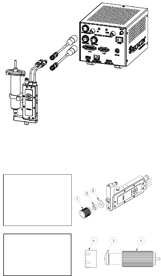
4.2 Setup
WARNING: Before starting the Jet Valve System, carefully read
through this user guide and pay attention to the warning and caution
notices.
Step 1:
• Using the provided nozzle
adjustment tool (1) to
remove the nozzle
adjustment nut/bushing
assembly (2) and
protective nylon washer
(3).
Step 2:
• Use the provided nozzle
installation tool (4) to
remove the nozzle bushing
(5) from the nozzle
adjustment nut (6).
Figure 3: Connection
10
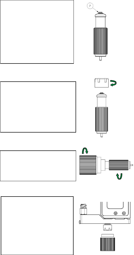
Step 5:
• Use the nozzle adjustment tool
to securely tighten the
assembly.
Step 3:
• Install the nozzle insert (7) to
the nozzle bushing. Caution:
the smaller end of the nozzle
inserts faces outward.
• Place the bushing/nozzle insert
assembly on the nozzle
installation tool in the vertical
position to prevent the nozzle
insert from dropping out.
Step 4:
• Slowly screw the nozzle
adjustment nut into the
bushing/nozzle insert assembly.
Caution: Continue to hold the
assembly in the vertical position
while hand-tightening the
nozzle adjustment nut.
Step 6:
• Screw the nozzle unit (nozzle
bushing, nozzle insert and
adjustment nut) to the fluid
manifold by hand (or use the
nozzle adjustment tool) for
about 3-4 turns only.
• Mount the valve on the XYZ
table
11
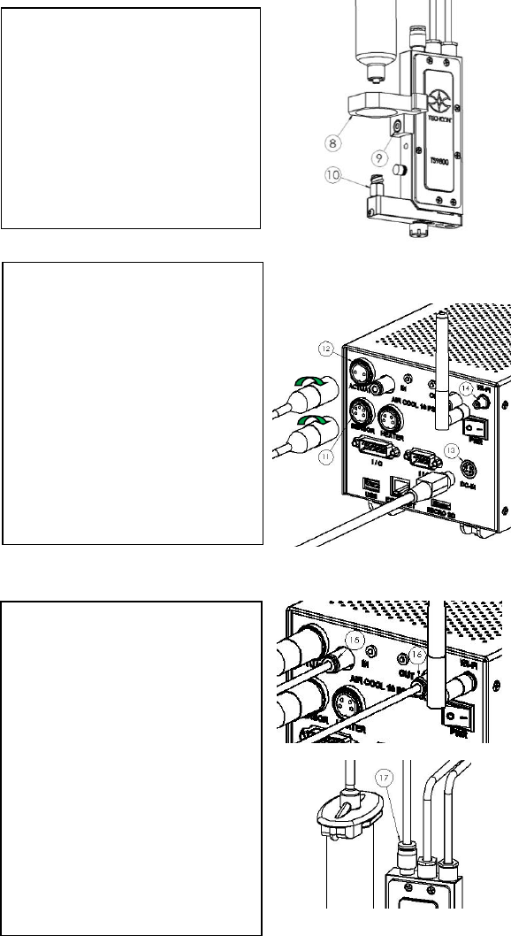
Step 7:
• Mount the syringe bracket (8)
by sliding it on the side of the
valve, then use the 3mm hex
wrench to install the provided
M4 screw (9) to secure the
bracket in place.
• Insert the syringe into the
bracket. Connect the syringe to
the valve inlet fitting (10).
Step 8:
• Connect the valve cables to the
controller. Sensor cable (6-to-5
pins) to the ‘SENSOR’ port
(11); Actuator cable (3-to-2
pins) to the ‘ACTUATOR’
port (12). Caution: After
connecting, tighten the locking
sleeve to secure the
connection.
• Connect the power cord to the
‘DC-IN’ port (13).
• Wi-Fi antenna (Not available)
Step 9:
• Connect the first ø4mm OD air
tubing from the air pressure
source to the ‘IN’ port (15).
Warning: This Air source
must be regulated and filter
(dry) separated from the air
pressure source for the material
syringe or reservoir.
• Connect the second ø4mm OD
air tubing from the ‘OUT’ port
(16) to the air fitting on top of
the Jet Valve (17).
• Turn up the air pressure for
cooling to the maximum of 10
psi.