ts9800-user-guide-7511-0360_A.pdf - 第22页
22 7. VALVE SETUP AND C LEANING 7.1 Valve rem oval. 1. Turn Off or d isconnect the fluid pressure the sy ringe/fluid su pply line from the material reservoir. 2. Swit ch -Off the contro l un it. 3. Disconn ect all valve …
21
Step 5:
Touch the up and down arrows to set the desired temperature. Then touch the
‘Accept’ icon to save and exit . Note: Maximum temperature setting is
90°C.
Step 6:
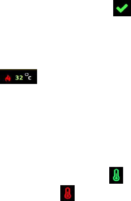
Watch the fluid manifold’s temperature reading at the bottom of the screen
. Once this temperature reaches the correct temperature setting, then
start the dispensing.
Warning: Do not touch nozzle or fluid manifold with your fingers once the
heater is turned on. Use provided tools for making any adjustment if necessary.
Step 7:
Touch the ‘Temperature’ icon again to turn OFF the heater and the icon will
turn back to red .
22
7. VALVE SETUP AND CLEANING
7.1 Valve removal.
1. Turn Off or disconnect the fluid pressure the syringe/fluid supply
line from the material reservoir.
2. Switch-Off the control unit.
3. Disconnect all valve cables.
4. Remove the valve from the XYZ table.
5. The valve can be now taken apart for cleaning, refer to section 7.3
for cleaning instructions.
6. After replacing the new valve or new control unit, repeat section 4.2
for setup and section 4.3 for nozzle calibration.
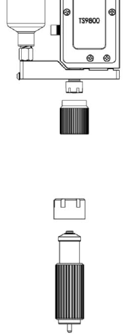
7.2 Installation of new nozzle insert.
1. Turn Off or Disconnect pressure to material syringe.
2. Unscrew the Nut and bushing assembly from the fluid manifold using
the nozzle adjustment tool.
3. Unscrew the nozzle bushing/insert assembly from the nozzle adjustment
nut using the nozzle installation tool.
4. Remove the nozzle insert from the nozzle bushing.
23
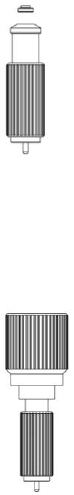
5. Place new nozzle insert on the nozzle bushing with the smaller end
facing outward and screw the assembly back into the nozzle adjustment
nut using provided tools. Caution: Keep the assembly in vertical
position while tightening to keep the nozzle seating in the proper
position. Use both tools to help torque the bushing onto the nut.
6. Screw the nozzle assembly unit back onto the fluid manifold and repeat
section 4.3 for nozzle calibration.
7. Re-connect or turn On the fluid supply and pressure. Run the several
purge cycles to remove air bubble from the nozzle replacement. Wipe
and Clean the nozzle tip and the system is now ready for dispensing.
Attention: Inspect the nozzle’s cleanliness under microscope if available.
7.3 Cleaning
WARNING:
• Proper gloves and eye protection must be worn before
disassembling the valve for cleaning.
• Never use wire brushes or machines that cause surface abrasion.
Unsuitable cleaning fluids may damage the valve. Before using
extremely aggressive cleaning liquids or solvents, make sure to
check that all fluid contacting parts are compatible.
The following cleaning tool kit (9800-CLEANKIT-XX) which consists
of the following:
1. Pin Vise
2. Cleaning wires (XX will designate the wire diameter)
3. Cleaning brush