ts9800-user-guide-7511-0360_A.pdf - 第46页
46 10.4 DB-15 Connector func tions NOTE: Digital ou tputs require a pull up re sistor to the positive supply of the recei ving devi ce. PIN F unction I/O TYPE Description Leve ls 1 GND 2 TR IGG ER_ IN I DI Trigger dispen…
45
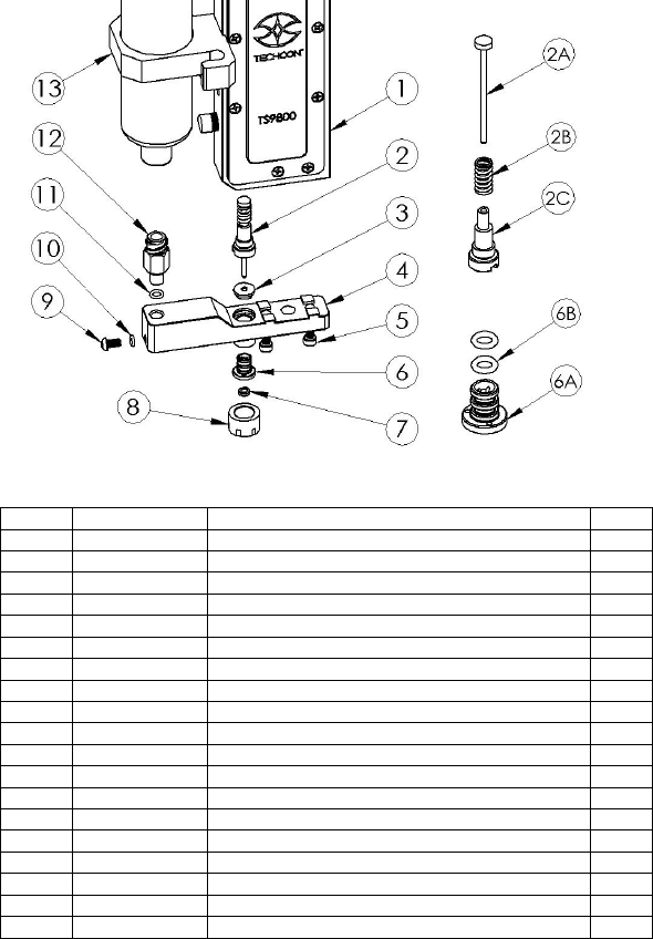
10.3 Jet Valve’s parts list
ITEM
PART NO.
DESCRIPTION
QTY
1
7511-9100
ASSEMBLY, VALVE BODY
1
2
7511-9140-15
ASSEMBLY, TAPPET TT15, 1.5MM TIP
1
2A
7511-0500-15
TAPPET TT15, TUNGSTEN CARBIDE, 1.5MM
1
2B
3300-0632
TAPPET SPRING
1
2C
7511-0490
TAPPET BUSHING
1
3
3300-0635
TAPPET SEAL
1
4
7511-0630
FLUID MANIFOLD, W/O HEATER, SS
1
5
2800-0981
MOUNTING SCREW, FLUID MANIFOLD
2
6
7511-9170
ASSEMBLY, NOZZLE BUSHING, SS
1
6A
7511-0480
NOZZLE BUSHING, SS
1
6B
3300-0662
O-RING, NOZZLE BUSHING
2
7
7511-0140-XX
NOZZLE INSERT
1
8
7511-0470
ADJUSTMENT NUT
1
9
2800-0980
PLUG SCREW (ITEM # 9&10 ARE ONE UNIT)
1
10
2800-0980
O-RING (ITEM # 9&10 ARE ONE UNIT)
-
11
3300-0662
O-RING, LUER LOCK FITTING
1
12
TSD931-63
LUER LOCK FITTING
1
13
7511-0530
SYRINGE BRACKET
1
14
2800-0936
MOUNTING SCREW, SYRINGE BRACKET
1
46
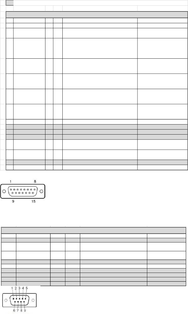
10.4 DB-15 Connector functions
NOTE: Digital outputs require a pull up resistor to the positive supply of the receiving device.
PIN Function I/O TYPE Description Levels
1 GND
2 TRIGGER_IN I DI
Trigger dispensing process from outside device
as external Robot or PLC
24V Valve IDLE
0V Valve DISPENSING
3 TRIGGER OUT O DI
Trigger to outside device as high speed camera.
The trigger signal is a sqare wave that is high
when the tappet lifts up, low when the tappet
closes.
+V when tappet lifts
OV when tappet closes
4 DISPENSING_CTRL I DI Controls the dispensing process
24V dispensing normal
operation
0V Dispengin aborted
5 ERROR OUT O DI Signal if any error or warning are present
0V Error/Warning Active
24V No Error/Warning has
occurred
6
TEMPERATURE
STATUS
O DI
Signals when nozzle heater is active is the
temperature of the heater has reached the
target tempetature entered in the menu
0V Target not reached
24V Target reached within
0.5C
7 REMOTE TEMP_IN I AN
Remotely set temperature on the nozzle heater
when heater has been switched ON (control
signal on PIN 12)
0 - 90C Range
200mV = 10C
8 +24V 200mV = 10C
9 NC
10 NC
11 NC
12 HEATER CONTROL I DI Control the heaters to either turn it ON or OFF
0V Heater ON
24V Heater OFF
13 VALVE OVERTEMP O DI
Signals when the piezo temperautre has
exceed the +85C operation limit
0V Temperature exceeded
24V Temperature within range
14 NC
15 GND
PIN Function
1 NC
2 RS232_RX I DI
RS232 Transmitter line on the external device/ Receiver on the JetValve Controler
RS-232 level compatible
3 RS232_TX O DI
RS232 Receiver line on the external device/ Transmitter on the JetValve Controler
RS-232 level compatible
4 NC
5 GND
6 NC
7 NC
8 NC
9 NC
DB 15 CONNECTOR
DB 9 CONNECTOR
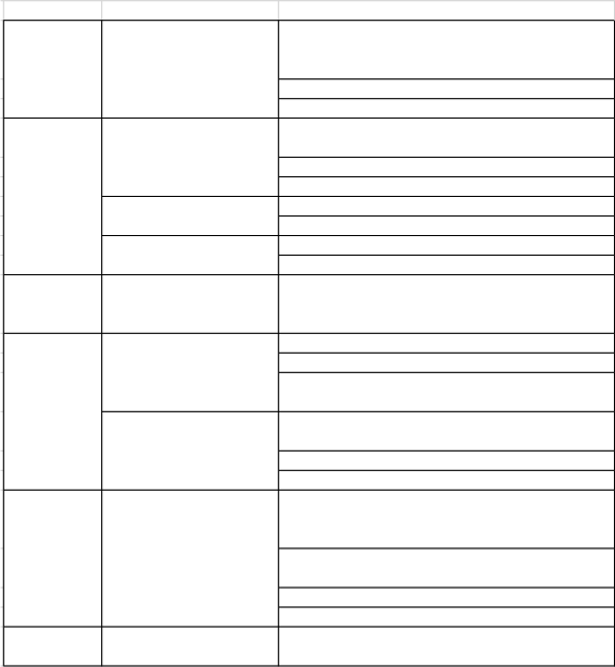
10.4 DB-9 Connector functions
PIN Function
I/O TYPE Description Levels
1 NC
2 RS232_RX I DI
RS232 Transmitter line on the external device/
Receiver on the JetValve Controler
RS-232 level compatible
3 RS232_TX O DI
RS232 Receiver line on the external device/
Transmitter on the JetValve Controler
RS-232 level compatible
4 NC
5 GND
6 NC
7 NC
8 NC
9 NC
DB 9 CONNECTOR
47
11. TROUBLE SHOOTING
11.1 General problems
PROBLEM WHAT & WHERE SUGGESTION
Piezo Over Heating, slow down dispense parameters.
Adjust longer dwell time (wait for temperature to drop
before starting again)
Intermittent, RTD connection may have a problem
Check connection of Sensor cable
loosen screws and re-align manifold
Replacing Tappet seal
Replace Tappet
Re-calibrate
Replace Tappet
Air cool is kicking On (normal)
ERROR message displayed (see Error problem)
REBOOTING
Controller keeps on
rebooting
Disconnect actuator cable, if controller reboot and stay
on the Piezo is shorted (Please Return valve to Techno
for evaluation)
Check connection of actuator cable
Manual dispensing must be in Dot Mode
Line Mode required external trigger, check external
triggering device
Nozzle maybe clogged
Syringe pressure must be On or connected
Re-calibrate
System must be On since the valve is in a Normally
Open without power
Make sure the Valve Close icon in the main menu is in
the Close Mode
Tighten up nozzle nut assembly and re-calibrate
Refer to Leakage section
FREEZES
Touch screen froze
If system froze up please reset using the On/Off switch
on the back of the controller
Valve not running
Valve running but nothing
come out
NOT
DISPENSING
DISPENSING
W/OUT
ACTIVATION
Drops or stream of material
coming out from the nozzle
Readout on controller
Between valve body and
Manifold
Nozzle
Air from valve
LEAKAGE
ERROR