ts9800-user-guide-7511-0360_A.pdf - 第47页
47 11. TROUBLE SH OOTING 11.1 General problem s PROBLEM WHAT & WHERE SUGGES TION Piezo Over H eating , slow down di spen se p arameters. Ad ju st long er d well ti me ( wait fo r tem per ature to dr op before startin…
46
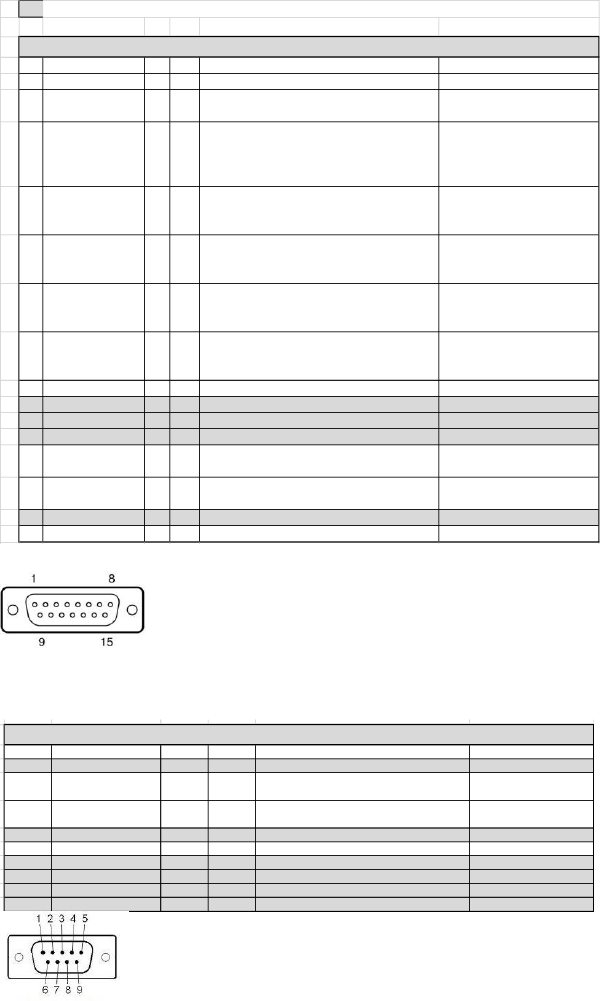
10.4 DB-15 Connector functions
NOTE: Digital outputs require a pull up resistor to the positive supply of the receiving device.
PIN Function I/O TYPE Description Levels
1 GND
2 TRIGGER_IN I DI
Trigger dispensing process from outside device
as external Robot or PLC
24V Valve IDLE
0V Valve DISPENSING
3 TRIGGER OUT O DI
Trigger to outside device as high speed camera.
The trigger signal is a sqare wave that is high
when the tappet lifts up, low when the tappet
closes.
+V when tappet lifts
OV when tappet closes
4 DISPENSING_CTRL I DI Controls the dispensing process
24V dispensing normal
operation
0V Dispengin aborted
5 ERROR OUT O DI Signal if any error or warning are present
0V Error/Warning Active
24V No Error/Warning has
occurred
6
TEMPERATURE
STATUS
O DI
Signals when nozzle heater is active is the
temperature of the heater has reached the
target tempetature entered in the menu
0V Target not reached
24V Target reached within
0.5C
7 REMOTE TEMP_IN I AN
Remotely set temperature on the nozzle heater
when heater has been switched ON (control
signal on PIN 12)
0 - 90C Range
200mV = 10C
8 +24V 200mV = 10C
9 NC
10 NC
11 NC
12 HEATER CONTROL I DI Control the heaters to either turn it ON or OFF
0V Heater ON
24V Heater OFF
13 VALVE OVERTEMP O DI
Signals when the piezo temperautre has
exceed the +85C operation limit
0V Temperature exceeded
24V Temperature within range
14 NC
15 GND
PIN Function
1 NC
2 RS232_RX I DI
RS232 Transmitter line on the external device/ Receiver on the JetValve Controler
RS-232 level compatible
3 RS232_TX O DI
RS232 Receiver line on the external device/ Transmitter on the JetValve Controler
RS-232 level compatible
4 NC
5 GND
6 NC
7 NC
8 NC
9 NC
DB 15 CONNECTOR
DB 9 CONNECTOR
10.4 DB-9 Connector functions
PIN Function
I/O TYPE Description Levels
1 NC
2 RS232_RX I DI
RS232 Transmitter line on the external device/
Receiver on the JetValve Controler
RS-232 level compatible
3 RS232_TX O DI
RS232 Receiver line on the external device/
Transmitter on the JetValve Controler
RS-232 level compatible
4 NC
5 GND
6 NC
7 NC
8 NC
9 NC
DB 9 CONNECTOR

47
11. TROUBLE SHOOTING
11.1 General problems
PROBLEM WHAT & WHERE SUGGESTION
Piezo Over Heating, slow down dispense parameters.
Adjust longer dwell time (wait for temperature to drop
before starting again)
Intermittent, RTD connection may have a problem
Check connection of Sensor cable
loosen screws and re-align manifold
Replacing Tappet seal
Replace Tappet
Re-calibrate
Replace Tappet
Air cool is kicking On (normal)
ERROR message displayed (see Error problem)
REBOOTING
Controller keeps on
rebooting
Disconnect actuator cable, if controller reboot and stay
on the Piezo is shorted (Please Return valve to Techno
for evaluation)
Check connection of actuator cable
Manual dispensing must be in Dot Mode
Line Mode required external trigger, check external
triggering device
Nozzle maybe clogged
Syringe pressure must be On or connected
Re-calibrate
System must be On since the valve is in a Normally
Open without power
Make sure the Valve Close icon in the main menu is in
the Close Mode
Tighten up nozzle nut assembly and re-calibrate
Refer to Leakage section
FREEZES
Touch screen froze
If system froze up please reset using the On/Off switch
on the back of the controller
Valve not running
Valve running but nothing
come out
NOT
DISPENSING
DISPENSING
W/OUT
ACTIVATION
Drops or stream of material
coming out from the nozzle
Readout on controller
Between valve body and
Manifold
Nozzle
Air from valve
LEAKAGE
ERROR
48
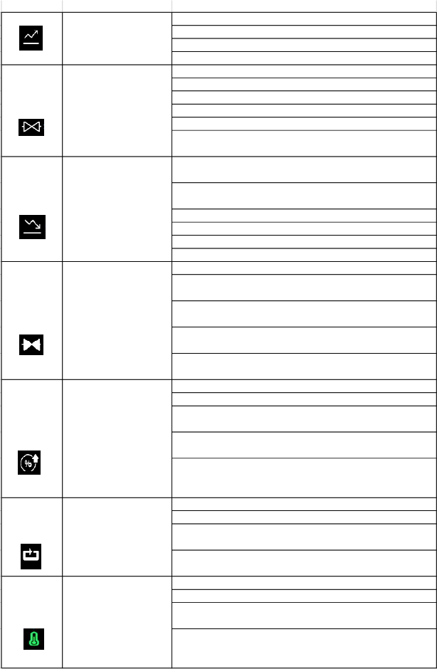
11.2 General functions
FUNCTIONS WHAT & WHY SUGGESTION
Minimum setting is 80 µs
Maximum setting is 1999 µs
Depend on viscosity start at about 300 µs
Rise time can also affect the accumulation or satelliting
Low viscosity material open time can be short 1-300 µs
Med viscosity material open time can be 200-1000 µs
High viscosity material open time can be 500-2500 µs
Smaller the shot smaller the open time
Bigger the shot larger the open time
minimize the open time to keep the shot as clean as possible
Minimum setting is 80 µs (smaller the value stronger the
punch/jetting)
Maximum setting is 1999 µs (larger the value slower the
punch/jetting)
Higher viscosity required stronger punch/jetting setting
Fall time can also affect the accumulation or satelliting
Slow down the fall time to reduce satelliting
Increase the fall to reduce accumulation
More important in the Line Mode
Important in Dot Mode if there are multiple pulses in one dot
(number of pulse in a certain time)
Single pulse/dot jetting delay time is not important since to
robot movement will take a longer time
The shorter the delay the closer the dots as it try to connect
the dots to form a line
The longer the delay the further the dots as it try to connect
the dots to form a line (it may not form solid line)
Higher lift for stronger punch/jet
The vale is more stable with lift higher than 40%
Higher lift will produce more volume (depending on open
time as well)
Lower lift will produce less volume (depending on open time
as well)
Higher lift and shorter fall time may be necessary for
dispense high viscosity material as well as stringy material
(Heater may help in bringing down the lift and fall time)
Dot Mode this can be set from 1 to 9999999 pulses
Line Mode it is not adjustable (default to pre set value)
One dot can be an accumulation of multiple pulses (e.g. one
dot can be 1 pulse or 20 pulses)
Multiple pulses can be use to increase the size of the dot or
use a larger diameter nozzle
Help stablize a process
Help lower the viscosity of a material for better flow
Help to reduce the stringiness of a material for better jetting
Consult w/ the material Mfg to prevent over heating of
material, we are not responsible for harden material in the
manifold and nozzle
LIFT
Percentage tappet lift
from fully closed to open
PULSE
A number of shots
HEATER
Heater on the manifold
OPEN
Time to allow material
to fill the cavity and
jetting out
FALL
Time to jet out the fluid
DELAY
Time between pulses
Time to lift the tappet
from fully closed to open
RISE