ts9800-user-guide-7511-0360_A.pdf - 第7页
7 3. TS9800 SYSTEM DESCRIP TION The TS9800 Series Jet V al ve is a Piezoelectric drive n, n on - co ntact dispensing valve capable of handling fluid at different viscosities. Jet V alve offers a fast jetting action produ…
6
2. UNPACKING AND INSPECTION
Carefully unpack the valve and examine the items contained in the carton.
These will include:
Inspect the unit for any damaged which may have occurred in transit. If
such damage has occurred, notify the carrier at once. Claim for damage
must be made by the consignee to the carrier and should be reported to the
manufacturer.
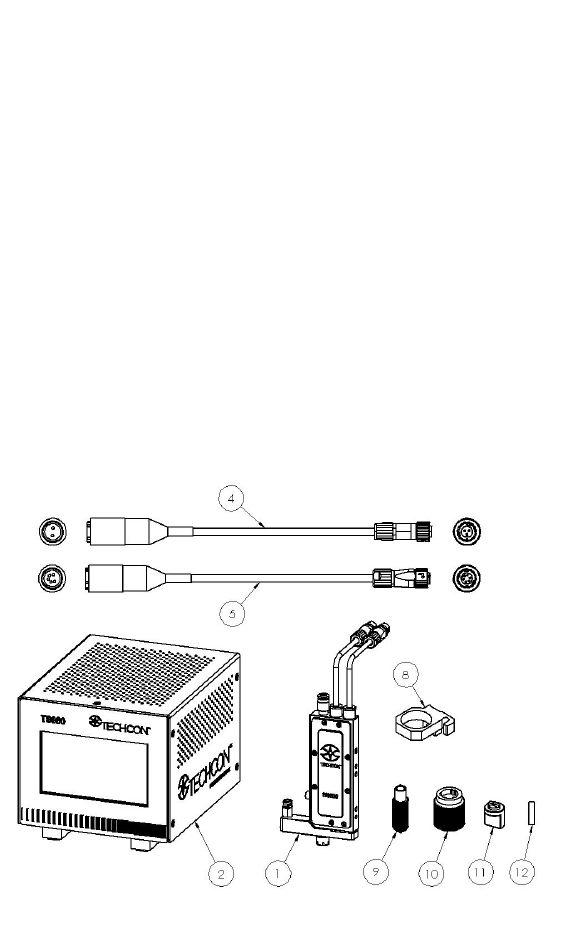
1) Jet Valve TS9800 (version shown below is without heater)
2) Jet Valve Controller TS980
3) Nozzle Insert (order separately)
4) Actuator Cable (3-to-2 pin connectors)
5) Sensor Cable (6-to-5 pin connectors)
6) Heater Cable (4-pin connectors). This cable is available only if
the jet valve with heating system was ordered
7) Heat Guard with M6 mounting screw. These items are available
only if the jet valve with heating system was ordered
8) Syringe Bracket with M4 mounting screw
9) Nozzle installation tool
10) Nozzle adjustment tool
11) Tappet changing tool
12) Tappet seal tool
13) Wi-Fi antenna (Not available currently)
14) Power Supply
15) User Guide
Figure 1: TS9800 Jet Valve System
7
3. TS9800 SYSTEM DESCRIPTION
The TS9800 Series Jet Valve is a Piezoelectric driven, non-contact
dispensing valve capable of handling fluid at different viscosities. Jet Valve
offers a fast jetting action producing hundreds of accurate deposits less than
one second.
Every component of the valve was designed to the highest tolerances and
manufactured to the strictest degree of precision insuring world class
accuracy and repeatability in drop-to-drop dispensing volume.
Jet Valve’s compact size and modular design aids integration into robotic
systems. The valve features fully adjustable parameter settings, allowing the
operator to change the jetting properties for different fluid types and
optimize the process for repeatable dispensing.
A variety of nozzles shape and sizes along with different tappet
configurations provides a wide spectrum of output jet deposits.
8
4. SET-UP INSTRUCTIONS
4.1 Mounting & Connection
The TS9800 Series Jet Valve should be used on an automated XYZ table. It
is very important that the valve is mounted on the Z-axis gantry, in a secure
manner, that will not allow loosening during dispense operation.
Mount the valve to the XYZ table bracket through the two tap holes (M4).
To prevent rusting condition, it is recommended that the bracket should be
made of stainless steel or galvanized steel or non-ferrous metals. The
screwing depth is about 6 mm.
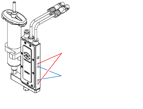
The connection of the TS9800 Jet Valve to the TS980 Controller is
done via the 3-pin plug and the 6-pin plug on the top of the valve. The
plugs are protected against mix-up by having different number of pins.
After connecting, the plug must be locked in place by turning the locking
nut on the cable’s mating connector a quarter of a turn in clockwise
direction.
The 3-pin cable supplies the power for the piezo stack from 0 VDC to
100 VDC (bipolar operation). The 6-pin cable transfers the data of the
integrated sensor inside the valve. Disconnection is done by first rotating
the locking nut on the cable’s mating connector a quarter of a turn in
counter-clockwise direction, then gently pull the connector axially
backwards Caution: Never disconnect the cables from the valve while
the system is still dispensing, this will lead to the damage of the valve
and the control unit. If the system is not operating, you can disconnect
the valve and the control unit.
Figure 2: Mounting
Mount the bracket to the two sets of
mounting holes:
2x thread M4
Thread depth 6mm
Distance to center 45mm
2x ø4mm dowel pin holes
Hole depth 6mm
Distance to center 31mm