ts9800-user-guide-7511-0360_A.pdf - 第9页
9 4 .2 Setup WARNING: B ef ore starting th e Jet Val ve System, carefully read through this u ser gui de and pay atten ti on to the warning and caution no tic es . Step 1: • Using th e provided nozzle adjustment tool (1)…
8
4. SET-UP INSTRUCTIONS
4.1 Mounting & Connection
The TS9800 Series Jet Valve should be used on an automated XYZ table. It
is very important that the valve is mounted on the Z-axis gantry, in a secure
manner, that will not allow loosening during dispense operation.
Mount the valve to the XYZ table bracket through the two tap holes (M4).
To prevent rusting condition, it is recommended that the bracket should be
made of stainless steel or galvanized steel or non-ferrous metals. The
screwing depth is about 6 mm.
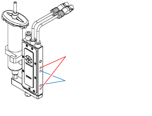
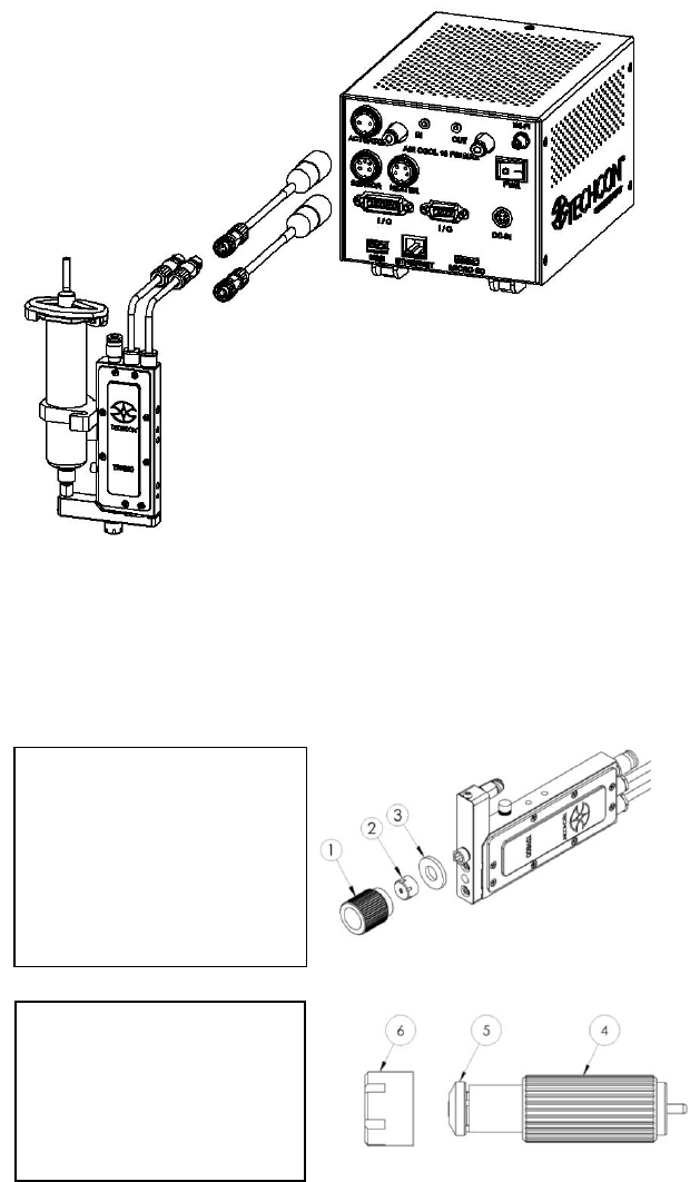
The connection of the TS9800 Jet Valve to the TS980 Controller is
done via the 3-pin plug and the 6-pin plug on the top of the valve. The
plugs are protected against mix-up by having different number of pins.
After connecting, the plug must be locked in place by turning the locking
nut on the cable’s mating connector a quarter of a turn in clockwise
direction.
The 3-pin cable supplies the power for the piezo stack from 0 VDC to
100 VDC (bipolar operation). The 6-pin cable transfers the data of the
integrated sensor inside the valve. Disconnection is done by first rotating
the locking nut on the cable’s mating connector a quarter of a turn in
counter-clockwise direction, then gently pull the connector axially
backwards Caution: Never disconnect the cables from the valve while
the system is still dispensing, this will lead to the damage of the valve
and the control unit. If the system is not operating, you can disconnect
the valve and the control unit.
Figure 2: Mounting
Mount the bracket to the two sets of
mounting holes:
2x thread M4
Thread depth 6mm
Distance to center 45mm
2x ø4mm dowel pin holes
Hole depth 6mm
Distance to center 31mm
9
4.2 Setup
WARNING: Before starting the Jet Valve System, carefully read
through this user guide and pay attention to the warning and caution
notices.
Step 1:
• Using the provided nozzle
adjustment tool (1) to
remove the nozzle
adjustment nut/bushing
assembly (2) and
protective nylon washer
(3).
Step 2:
• Use the provided nozzle
installation tool (4) to
remove the nozzle bushing
(5) from the nozzle
adjustment nut (6).
Figure 3: Connection
10
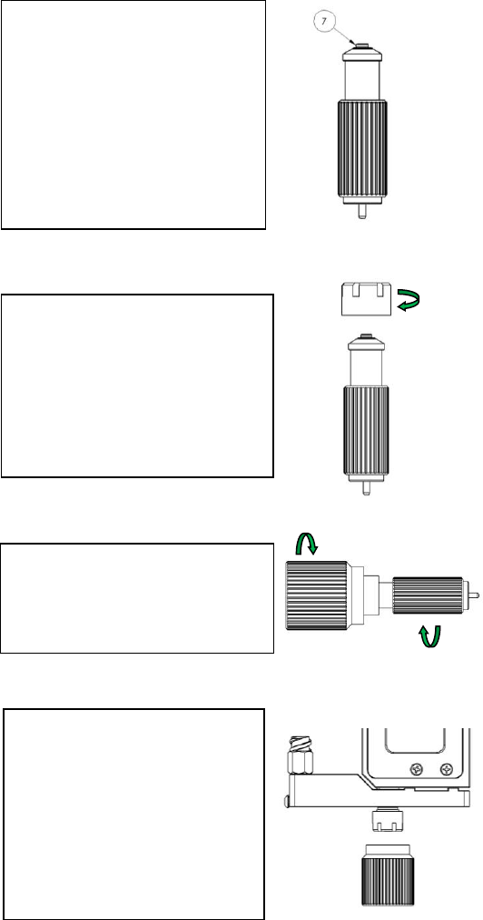
Step 5:
• Use the nozzle adjustment tool
to securely tighten the
assembly.
Step 3:
• Install the nozzle insert (7) to
the nozzle bushing. Caution:
the smaller end of the nozzle
inserts faces outward.
• Place the bushing/nozzle insert
assembly on the nozzle
installation tool in the vertical
position to prevent the nozzle
insert from dropping out.
Step 4:
• Slowly screw the nozzle
adjustment nut into the
bushing/nozzle insert assembly.
Caution: Continue to hold the
assembly in the vertical position
while hand-tightening the
nozzle adjustment nut.
Step 6:
• Screw the nozzle unit (nozzle
bushing, nozzle insert and
adjustment nut) to the fluid
manifold by hand (or use the
nozzle adjustment tool) for
about 3-4 turns only.
• Mount the valve on the XYZ
table