Nordson_EFD_OptiSure_Operating_Manual - 第12页
OptiSure Automated Optical Inspection 12 www.nordsonefd.com info@nordsonefd.com +1-401-431-7000 Sales and service of Nordson EFD dispensing systems are available worldwide. Overview of the OptiSur eAOI Functions Click t…
OptiSure Automated Optical Inspection
11www.nordsonefd.com info@nordsonefd.com +1-401-431-7000 Sales and service of Nordson EFD dispensing systems are available worldwide.
Using the Center Button for LaserC Setup
On systems with Laser C, the Laser Detect Setup window has a Center button that can be used for more precise
laser calibration. Using the Center button is optional, but is recommended to obtain the most accurate calibration.
Follow these steps to use the Center button during Laser C setup.
PREREQUISITES
You have completed “Setting Up the Confocal Laser” on page10.
You have completed steps 1–3 of the Laser Detect Setup wizard.
#
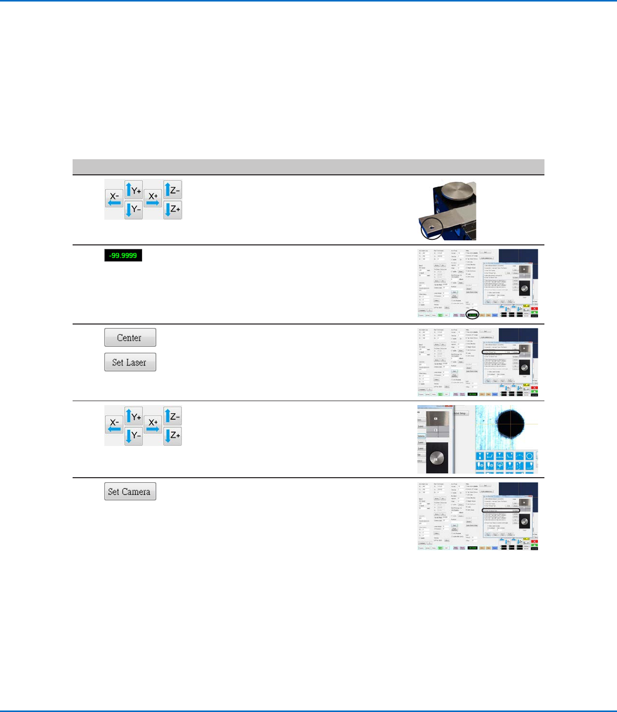
Click Step Reference Image
1
• Move the laser to the centering hole located on
the tip detector.
2 • Observe the laser readout value. If the laser
readout shows -99.999, the laser is successfully
passing through the hole. If not, the laser is not
precisely centered.
3
>
• Click CENTER next to Set Laser.
The laser moves in two directions (left to right,
then north to south) to calibrate itself and then
moves to the center of the hole.
• Click SET LASER.
4 • Jog the camera to center the crosshairs over
the centering hole located on the tip detector.
• Click SET CAMERA.
The laser-to-camera offset is now precisely
calibrated.
• Complete the remaining steps of the Laser
Detect Setup wizard and close the window after
you have completed all the steps.
Setting Up the Confocal Laser (continued)

OptiSure Automated Optical Inspection
12 www.nordsonefd.com info@nordsonefd.com +1-401-431-7000 Sales and service of Nordson EFD dispensing systems are available worldwide.
Overview of the OptiSureAOI Functions
Click the Arrow icon, then right-click in the Primary View screen to view the Arrow menu.
Arrow Menu Item Description Refer to...
Delete All
Deletes all arrows associated with a mark image. n/a
Image
Threshold
Allows you to isolate a specific portion of an image
for future adjustment; the isolated portion remains
visible on the screen when you are adjusting the
parameters in an Arrow dialog box:
• Recommended for use in tandem with any Arrow
Type
• Provides more accurate results than Template /
Area
“Using Image
Threshold” on
page13
Add New
Arrow
Adds an arrow to a mark image; added arrows can be
manipulated individually or collectively to improve the
system’s ability to find a mark image, or to optically
check a dispense.
Select the arrow type to use based on the
characteristics of the mark image.
“Using the Arrow
Types” on page14
Color
Changes the color of the on-screen arrows, circles,
and other visual aids of the Arrow functions.
n/a
Location of the Arrow icon on the Camera tab (turns yellow when selected) and the resulting menu when you right-click in the
Primary View screen
OptiSure Automated Optical Inspection
13www.nordsonefd.com info@nordsonefd.com +1-401-431-7000 Sales and service of Nordson EFD dispensing systems are available worldwide.
Using Image Threshold
Image Threshold allows you to view changes to a mark image as you make adjustments. This feature can be used
alone or in tandem with an Add New Arrow function. Nordson EFD recommends first using Image Threshold before
using some of the Arrow Type functions, so that you can view the changes to the image on the screen.
NOTE: A quicker alternative to using Image Threshold is to use the Threshold slider inside each Arrow Type dialog
box. If you want to use the quicker method, do not enable Image Threshold.
PREREQUISITES
The mark image you want to adjust is saved in the Mark Library.
# Click Step Reference Image
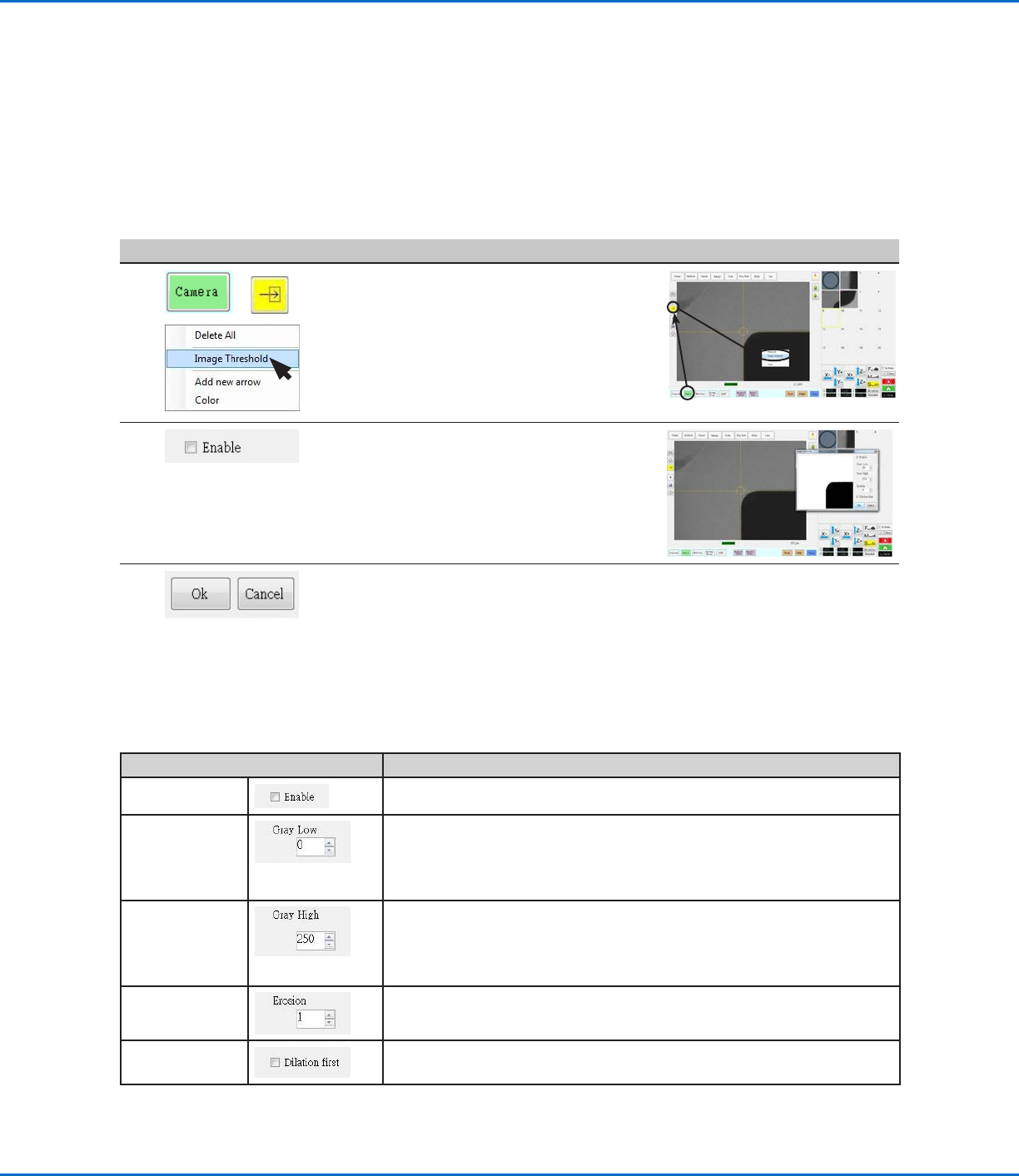
1
> >
• Click CAMERA to go to the camera
screen.
• Click the ARROW icon.
• In the Primary View screen, right-click
and select IMAGE THRESHOLD.
The Image Threshold window opens.
2 • In the Image Threshold window, select
the Enable checkbox.
• Adjust the Image Threshold settings
until you have successfully isolated
the mark. Refer to “Image Threshold
Window Parameters” for details.
3 • Click OK to save the adjustments or
click CANCEL to exit without saving.
Image Threshold Window Parameters
Parameter Function
Enable
If checked, enables the Image Threshold function.
Gray Low Adjusts the minimum value of the threshold — the lower the setting, the
less visible the image will be; when a valid setting is entered, the image is
visible on the screen.
Range: 0–255 (0 is full dark; 255 is full white)
Gray High
Adjusts the maximum value of the threshold — if the maximum value is
exceeded, the image will not be visible; when a valid setting is entered, the
image is visible on the screen.
Range: 0–255
Erosion
Reduces and then enlarges the image to remove impurities (as long as
Dilation First is not checked).
Dilation
If checked, enlarges and then reduces the image to remove impurities.