Nordson_EFD_OptiSure_Operating_Manual - 第15页
OptiSure Automated Optical Inspection 15 www.nordsonefd.com info@nordsonefd.com +1-401-431-7000 Sales and service of Nordson EFD dispensing systems are available worldwide. Arrow Menu T ype Selection Recommended Use Refe…
OptiSure Automated Optical Inspection
14 www.nordsonefd.com info@nordsonefd.com +1-401-431-7000 Sales and service of Nordson EFD dispensing systems are available worldwide.
Using the Arrow Types
The Add New Arrow icon accesses advanced features that allow you to:
• Add details to a mark image to improve the system’s ability to match the mark image to the corresponding
location on a workpiece.
• Verify the width, length, or depth of a dispense based on parameters saved in a mark image.
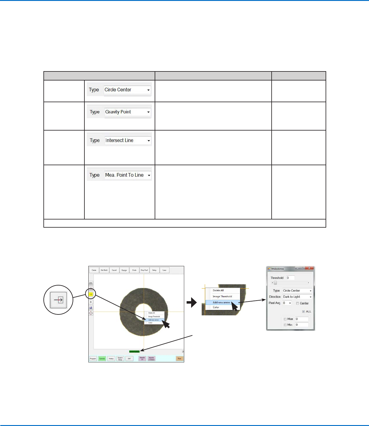
There are five types of arrow function, shown below. An example procedure for using each function is provided.
Arrow Menu Type Selection Recommended Use Refer to...
Circle Center
Create a mark image that defines the
center of a circular area with poorly defined
boundaries.
“Circle Center
Example” on
page23
Gravity Point
Create two mark images on a line so that you
can use Fiducial Marks to ensure that line
dispenses are made down the center of a line,
regardless of its thickness.
“Gravity Point
Example” on
page18
Intersect Line
Create a mark image for a workpiece that
does not have any obvious marks for the
system to find; in this case, you must use the
upper left and bottom right corners of the
workpiece to create marks.
“Intersect Line
Example” on
page37
Mea. Point To
Line
Create a mark image that allows you to
measure the width between any two points
on a line. Then, using the Arrow Check Point
command, the system can check the width
between the specified points; if the width
does not meet the criteria specified within the
mark image, the system takes the specified
action.
“Mea. Point To
Line Example” on
page43
Continued on next page
Accessing the Add New Arrow function on the Camera tab, and the resulting AOI Arrow parameter window
NOTE: Refer to “AOI Arrow
Window Elements” on
page16 for details.
NOTE: AOI measurements
are displayed here, and will
stay on the screen even if you
click outside the AOI feature.
However, if you click Needle XY
Adjust, Score will replace the AOI
measurement.
OptiSure Automated Optical Inspection
15www.nordsonefd.com info@nordsonefd.com +1-401-431-7000 Sales and service of Nordson EFD dispensing systems are available worldwide.
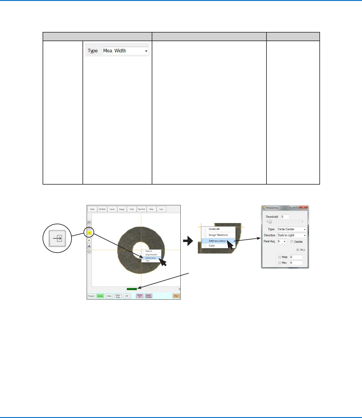
Arrow Menu Type Selection Recommended Use Refer to...
Mea. Width
(Automated
Optical
Inspection)
Create a mark image that sets the desired
width for a line; this mark image can then be
used as follows:
• When used with the Arrow Check
Point or Arrow Check Line commands,
the system can check the width of a
dispensed line; if the dispensed line does
not meet the criteria specified within
the mark image, the system takes the
specified action.
“Mea. Width
Example for
Verifying Line
Width” on
page48
• When used with the Auto Speed Setup,
Measure Width, and Auto Speed
commands, the system can automatically
adjust the speed of the dispenser to
maintain the desired line width for
specified line dispenses.
NOTE: This capability can be used only
when the main.bas file has been added
to the D:\ever_sr directory. Contact your
Nordson EFD representative to obtain
this file.
“Mea. Width
Example for
Dispense Width
Adjustment” on
page53
Using the Arrow Types (continued)
Accessing the Add New Arrow function on the Camera tab, and the resulting AOI Arrow parameter window
NOTE: Refer to “AOI Arrow
Window Elements” on
page16 for details.
NOTE: AOI measurements
are displayed here, and will
stay on the screen even if you
click outside the AOI feature.
However, if you click Needle XY
Adjust, Score will replace the AOI
measurement.
OptiSure Automated Optical Inspection
16 www.nordsonefd.com info@nordsonefd.com +1-401-431-7000 Sales and service of Nordson EFD dispensing systems are available worldwide.
Parameter Applicability Description
Threshold
Range: 0–255
All arrow types As long as Image Threshold is not enabled, you
can use this parameter to adjust the mark image
automatically. If Image Threshold is enabled, this
parameter is disabled. Refer to “Using Image
Threshold” on page13 for details.
Type
n/a Sets the arrow type. Refer to “Using the Arrow Types”
on page14 for an explanation of each.
Direction
Other value: Light to
Dark
All arrow types The direction of the light on the thresholded image
that matches the direction of the inserted arrow. For
accurate results, the selected Direction must match
the direction of that inserted arrow points toward.
EXAMPLES:
• If (1) an isolated mark is black, and (2) the empty
space around it is white, and (3) the inserted
arrow points inward toward the mark, then the
light direction is white to black, in which case the
correct selection for Direction is LIGHT TO DARK.
• If (1) an isolated mark is white, and (2) the empty
space around it is black, and (3) the inserted arrow
points inward toward the mark, then light direction
is black to white, in which case the correct
selection for Direction is DARK TO LIGHT.
NOTE: If you enable Image Threshold, the system
converts the image to black and white, where black
is the isolated mark and white is the dead space, or
vice versa.
Continued on next page
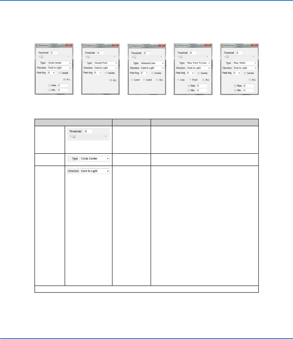
AOI Arrow Window Elements
The parameters in the AOI Arrow window vary depending on the selected arrow Type.
Using the Arrow Types (continued)
Circle Center
parameters
Gravity Point
parameters
Intersect Line
parameters
Measure Point to Line
parameters
Measure Width
parameters