Nordson_EFD_OptiSure_Operating_Manual - 第17页
OptiSure Automated Optical Inspection 17 www.nordsonefd.com info@nordsonefd.com +1-401-431-7000 Sales and service of Nordson EFD dispensing systems are available worldwide. AOI Arrow Window Elements (continued) Using the…
OptiSure Automated Optical Inspection
16 www.nordsonefd.com info@nordsonefd.com +1-401-431-7000 Sales and service of Nordson EFD dispensing systems are available worldwide.
Parameter Applicability Description
Threshold
Range: 0–255
All arrow types As long as Image Threshold is not enabled, you
can use this parameter to adjust the mark image
automatically. If Image Threshold is enabled, this
parameter is disabled. Refer to “Using Image
Threshold” on page13 for details.
Type
n/a Sets the arrow type. Refer to “Using the Arrow Types”
on page14 for an explanation of each.
Direction
Other value: Light to
Dark
All arrow types The direction of the light on the thresholded image
that matches the direction of the inserted arrow. For
accurate results, the selected Direction must match
the direction of that inserted arrow points toward.
EXAMPLES:
• If (1) an isolated mark is black, and (2) the empty
space around it is white, and (3) the inserted
arrow points inward toward the mark, then the
light direction is white to black, in which case the
correct selection for Direction is LIGHT TO DARK.
• If (1) an isolated mark is white, and (2) the empty
space around it is black, and (3) the inserted arrow
points inward toward the mark, then light direction
is black to white, in which case the correct
selection for Direction is DARK TO LIGHT.
NOTE: If you enable Image Threshold, the system
converts the image to black and white, where black
is the isolated mark and white is the dead space, or
vice versa.
Continued on next page
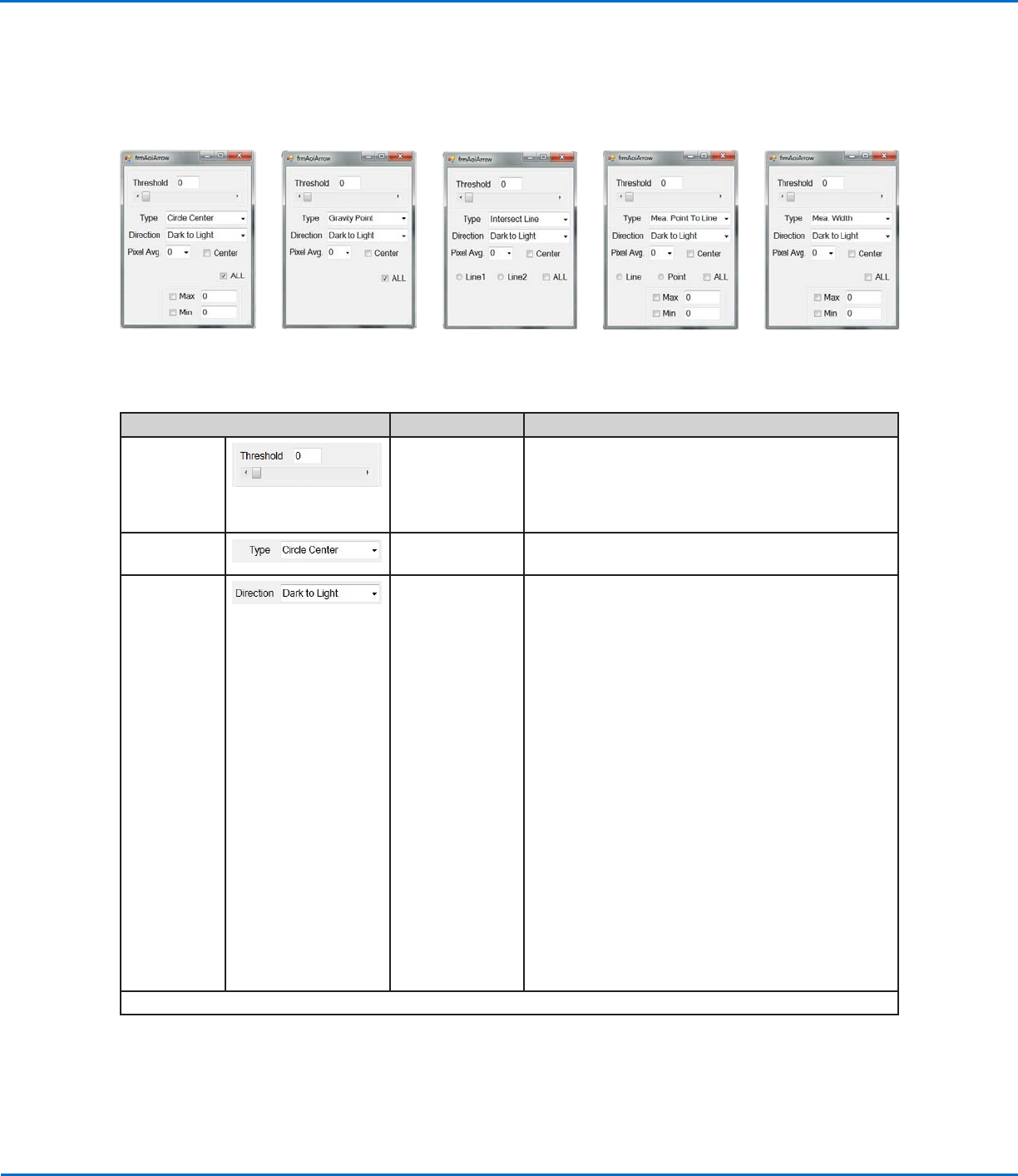
AOI Arrow Window Elements
The parameters in the AOI Arrow window vary depending on the selected arrow Type.
Using the Arrow Types (continued)
Circle Center
parameters
Gravity Point
parameters
Intersect Line
parameters
Measure Point to Line
parameters
Measure Width
parameters
OptiSure Automated Optical Inspection
17www.nordsonefd.com info@nordsonefd.com +1-401-431-7000 Sales and service of Nordson EFD dispensing systems are available worldwide.
AOI Arrow Window Elements (continued)
Using the Arrow Types (continued)
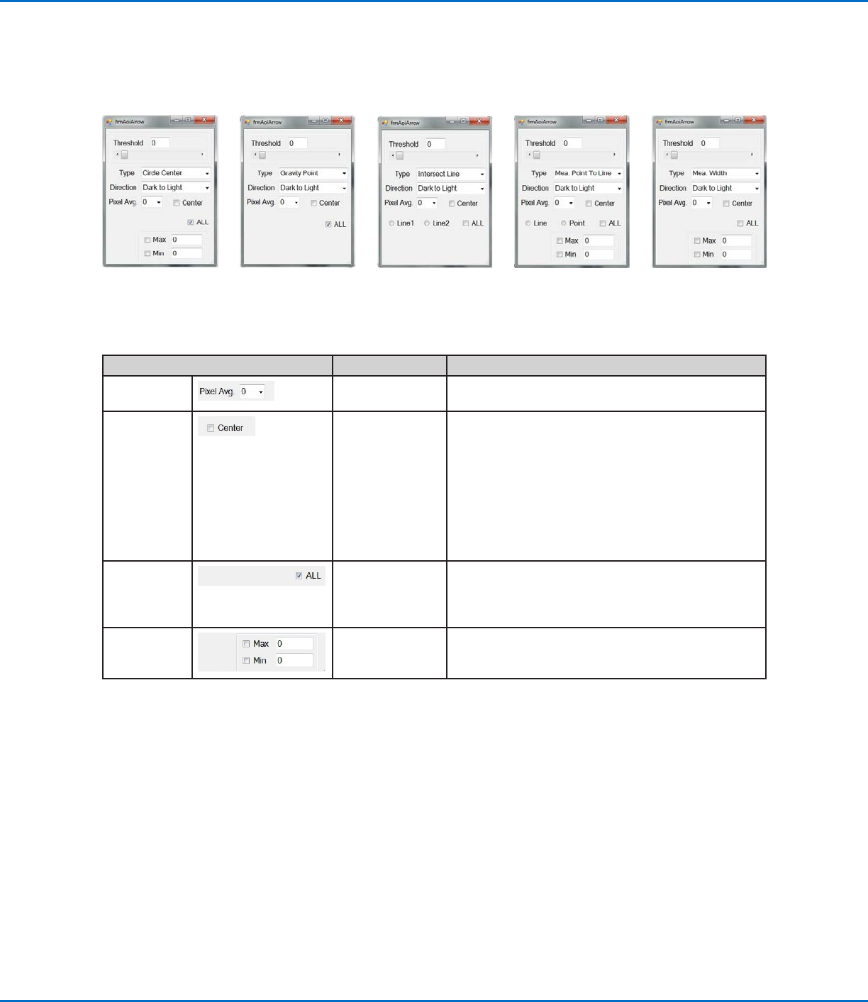
Parameter Applicability Description
Pixel Avg.
All arrow types Averages the pixel density, allowing higher accuracy
when the system searches for the mark.
Center
checkbox
All arrow types If enabled, the system attempts to use the mark
image to center the camera over the mark before
acting upon the data specified in an arrow feature. By
default, Center is deselected.
NOTE: Most arrow features also attempt to center a
mark, so enabling this feature might cause the system
to center the camera twice: Once using the mark
image in the mark library and then again using the
arrow feature.
ALL
checkbox
All arrow types If checked, the system adjusts any changed settings
for all the arrows. By default, ALL is deselected. This
setting must be selected before any other changes
are made in an AOI Arrow window.
Max and Min
checkboxes
Circle Center,
Mea. Point To
Line, Mea. Width
If checked, you can enter values to specify maximum
and minimum values for the selected arrow Type.
Circle Center
parameters
Gravity Point
parameters
Intersect Line
parameters
Measure Point to Line
parameters
Measure Width
parameters
OptiSure Automated Optical Inspection
18 www.nordsonefd.com info@nordsonefd.com +1-401-431-7000 Sales and service of Nordson EFD dispensing systems are available worldwide.
Gravity Point Example
Gravity Point is an OptiSureAOI feature that allows you to create two Fiducial Marks in the center of a line, one at
the beginning of the line and the other at the end of the line. Then, if a subsequent dispense must be made on a line
that is thicker or thinner, the system can dispense through the center of that line using the Fiducial Mark offsets.
PREREQUISITES
To learn how to use this feature, draw two lines of different thicknesses on a sheet of white paper and use it as a
workpiece template.
Using the Arrow Types (continued)
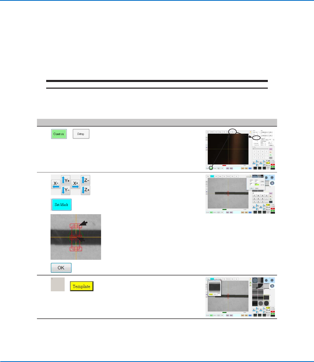
To Create a Gravity Point Mark Image
# Click Step Reference Image
1
>
• Click CAMERA > SETUP and enter a
lower score for SENSE (1 is used in
this example).
NOTE: You may need to adjust this
value based on the results as you
work through this procedure.
2
>
>
1.
2.
>
• Jog the camera to a location near
the beginning of the thicker line.
• Click SET MARK, then click and
drag the red box (item 1) over the
line.
• Double-click the crosshairs in the
center of the red box (item 2) and
then enter the desired values for
Width and Height (20 and 60 in this
example).
• Click OK to save the values.
3
>
• Click a socket in the Mark Library to
save the mark, then click TEMPLATE
when the Template Match window
appears.
The system saves the image in the
Mark Library.
Continued on next page