Nordson_EFD_OptiSure_Operating_Manual - 第31页
OptiSure Automated Optical Inspection 31 www.nordsonefd.com info@nordsonefd.com +1-401-431-7000 Sales and service of Nordson EFD dispensing systems are available worldwide. # Click Step Reference Image 12 • Select the AL…
OptiSure Automated Optical Inspection
30 www.nordsonefd.com info@nordsonefd.com +1-401-431-7000 Sales and service of Nordson EFD dispensing systems are available worldwide.
Using the Arrow Types (continued)
Positional Checking Example (continued)
To Create a Circle Center Mark Image (continued)
# Click Step Reference Image
7
3.
2.
1.
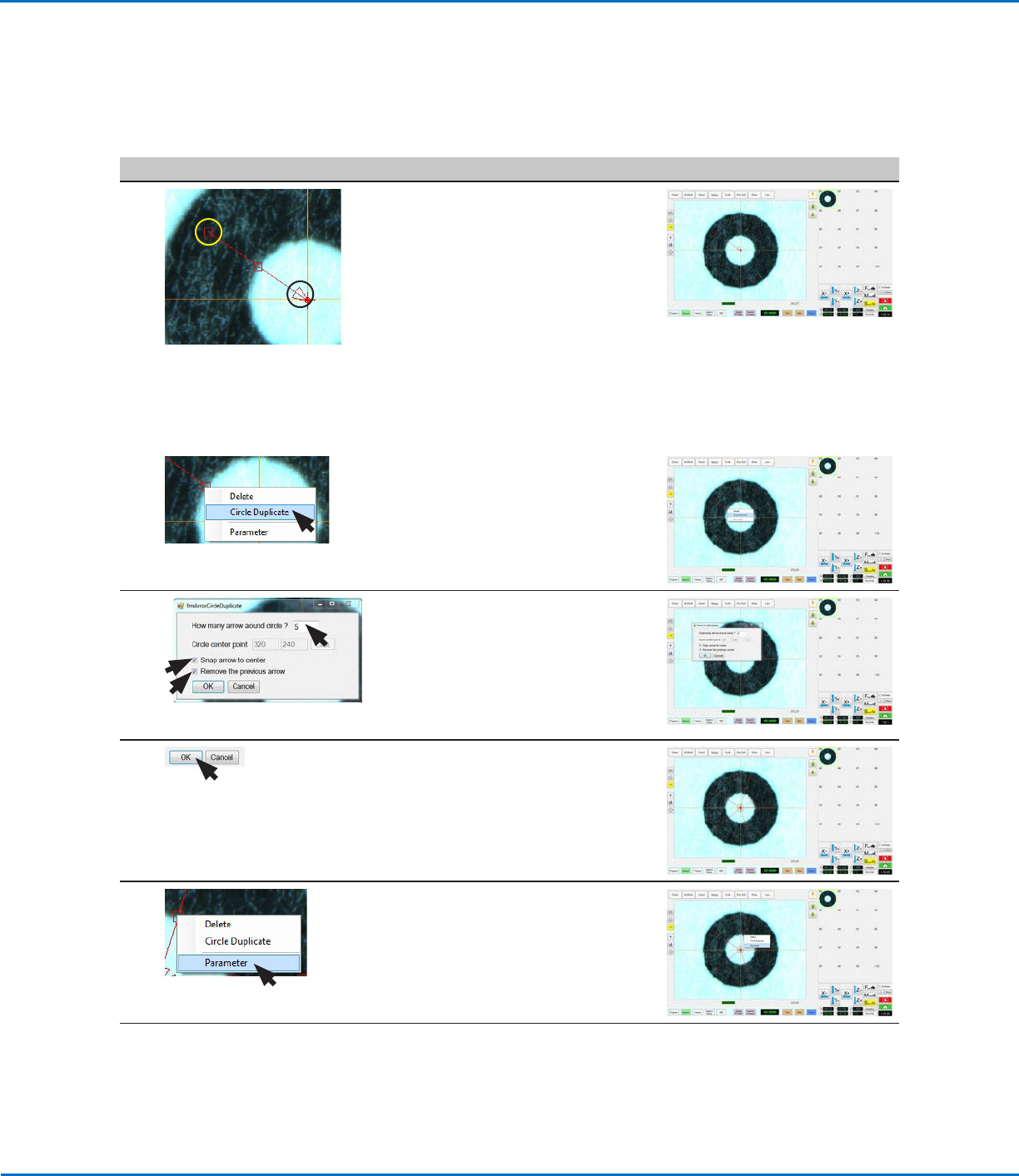
• Drag the triangle of the arrow (item 3)
close to the center of the circle.
• Drag the upper box of the arrow
(item1) such that the middle box
(item 2) is located on the outer
circumference of the circle.
NOTES:
- To move the entire arrow, click and
drag the middle box (item 2).
- To elongate or shorten the arrow,
click and drag the triangle (item 3) or
the upper box (item 1).
8
4.
• Right-click on a box on the
arrow (item4) and select CIRCLE
DUPLICATE.
The Arrow Circle Duplicate window
opens.
9 • Enter 5 for the number of arrows
around the circle.
• Select the SNAP ARROW TO CENTER
checkbox (checked by default).
• Select the REMOVE THE PREVIOUS
ARROW checkbox (checked by
default).
10 • Click OK.
Five arrows appear on the image.
11 • Right-click on any middle box of an
arrow and then select PARAMETER.
The AOI Arrow window opens.
Continued on next page
OptiSure Automated Optical Inspection
31www.nordsonefd.com info@nordsonefd.com +1-401-431-7000 Sales and service of Nordson EFD dispensing systems are available worldwide.
# Click Step Reference Image
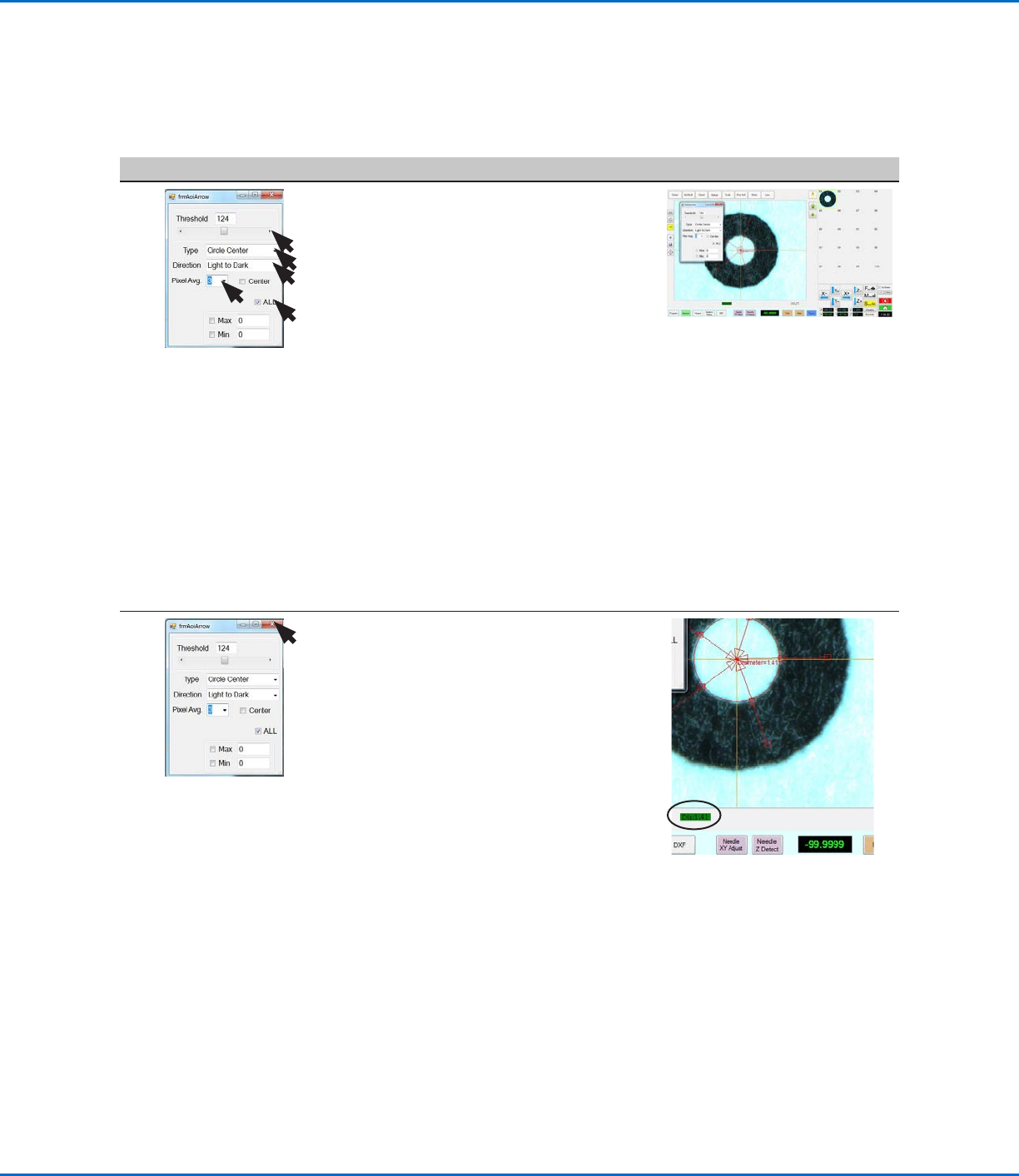
12
• Select the ALL checkbox (to cause the
system to enter the same settings for
all arrows).
• For Type, select CIRCLE CENTER.
• Select LIGHT TO DARK.
• Set PIXEL AVG to 3.
• Adjust THRESHOLD until the
circumference measurement appears
and is stable.
NOTES:
- Alternatively, you can use the Image
Threshold feature by right-clicking
in the Primary View screen and
selecting Image Threshold. Refer
to “Using Image Threshold” on
page13 for details.
- CENTER is not used in this example.
- MAX and MIN are not used in this
example but can be selected and
added if desired.
13 • Close the dialog box to save the
settings.
The system adds the circle diameter
and its value (item 4) to the mark
image of the circle and displays the
measurement at the bottom of the
Primary View screen (item 5).
The saved mark image now contains
additional data that will allow the
system to accurately find it upon
reaching its corresponding Find Mark
or Arrow Check Point command in a
program.
• Continue to “To Use Positional
Checking in a Program” on page32.
4.
5.
Using the Arrow Types (continued)
Positional Checking Example (continued)
To Create a Circle Center Mark Image (continued)
OptiSure Automated Optical Inspection
32 www.nordsonefd.com info@nordsonefd.com +1-401-431-7000 Sales and service of Nordson EFD dispensing systems are available worldwide.
To Use Positional Checking in a Program
# Click Step Reference Image
1
>
>
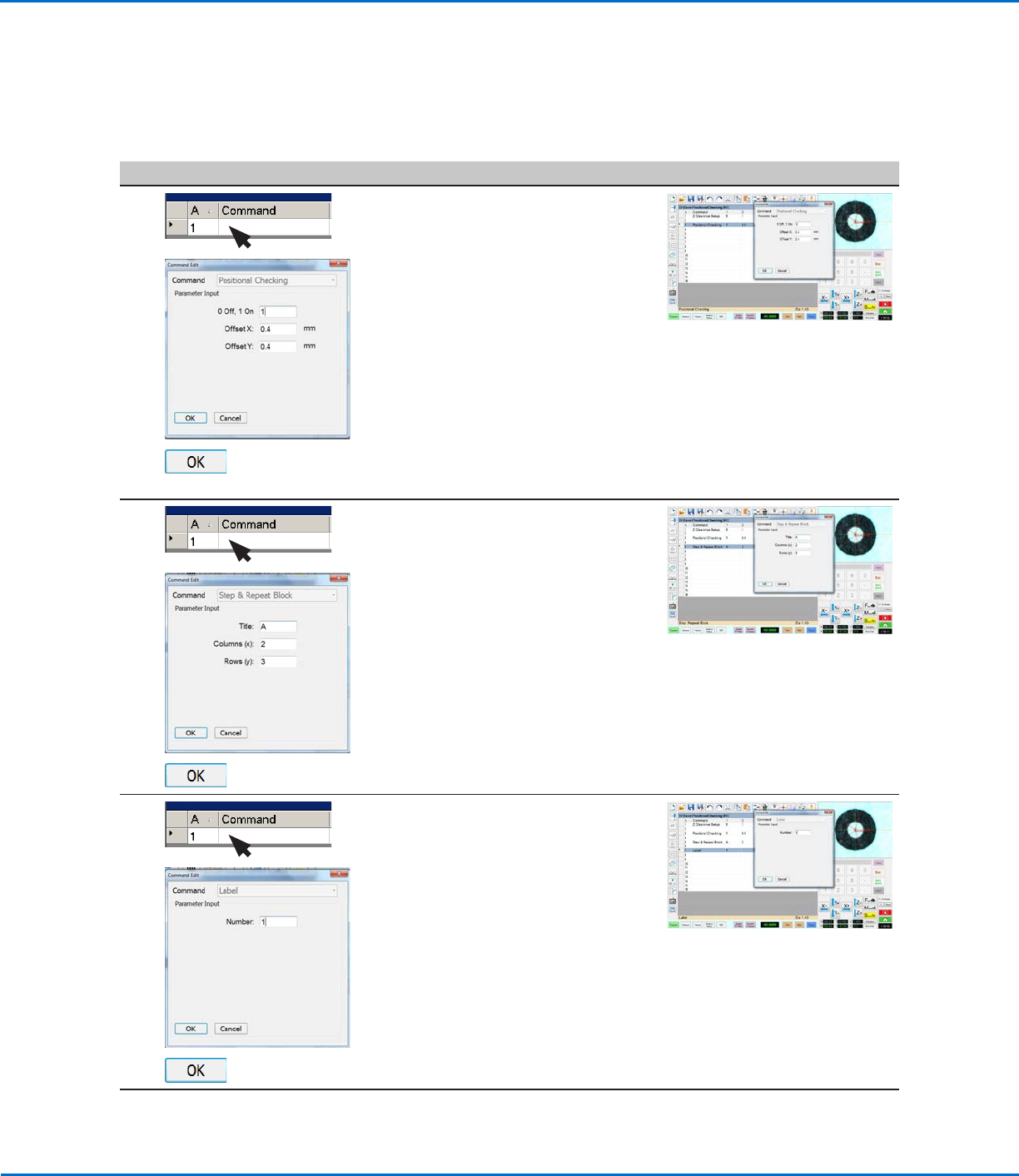
• At the beginning of the program,
insert a Positional Checking
command and enter the following:
- 1 ON
- OFFSET X: 0.4 (mm)
- OFFSET Y: 0.4 (mm)
• Click OK.
NOTES:
• The offset values are the maximum
allowable deviation of the inner dots
from the larger circle.
• This example program includes a
ZClearance Setup command, but it
is not required.
2
>
>
• Insert a Step & Repeat Block
command and enter the following:
- TITLE: A (in this example)
- COLUMNS (x): 2
- ROWS (y): 3
• Click OK.
3
>
>
• Insert a Label command and enter a
number (1, in this example).
• Click OK.
Continued on next page
Using the Arrow Types (continued)
Positional Checking Example (continued)