Nordson_EFD_OptiSure_Operating_Manual - 第37页
OptiSure Automated Optical Inspection 37 www.nordsonefd.com info@nordsonefd.com +1-401-431-7000 Sales and service of Nordson EFD dispensing systems are available worldwide. Intersect Line Example Intersect Line is an Opt…
OptiSure Automated Optical Inspection
36 www.nordsonefd.com info@nordsonefd.com +1-401-431-7000 Sales and service of Nordson EFD dispensing systems are available worldwide.
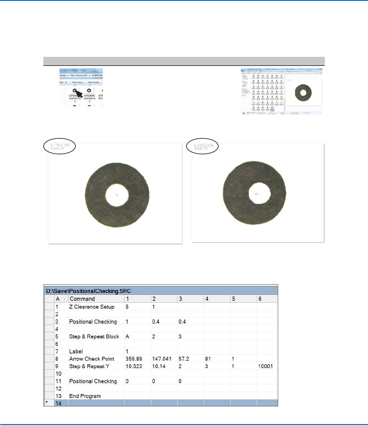
Example program using Positional Checking and Step & Repeat commands to check dispensed dots
# Click Step Reference Image
13
• Open an image to view more
information, including Diameter and
X and Y offsets. Example images
for both a passed and failed dot are
provided below.
Positional Checking Example (continued)
To Use Positional Checking in a Program (continued)
Using the Arrow Types (continued)
Location of diameter and offset details in the image of a dot that
PASSED a positional check
Location of diameter and offset details in the image of a dot
that FAILED a positional check
OptiSure Automated Optical Inspection
37www.nordsonefd.com info@nordsonefd.com +1-401-431-7000 Sales and service of Nordson EFD dispensing systems are available worldwide.
Intersect Line Example
Intersect Line is an OptiSureAOI feature that allows you to create mark images for a workpiece that does not have
any obvious features. To do so, you create marks using the corners and edges of the workpiece. This function also
works for creating marks for an R-shaped area.
NOTE: If the rounded corners are too large to use Intersect Line, try using the Edge Adjust command. Refer to the
operating manual for details.
PREREQUISITES
To learn how to use this feature, draw a large black rectangle with rounded corners on a sheet of white paper
and use it as a workpiece template.
To Create an Intersect Line Mark Image
# Click Step Reference Image
1
> >
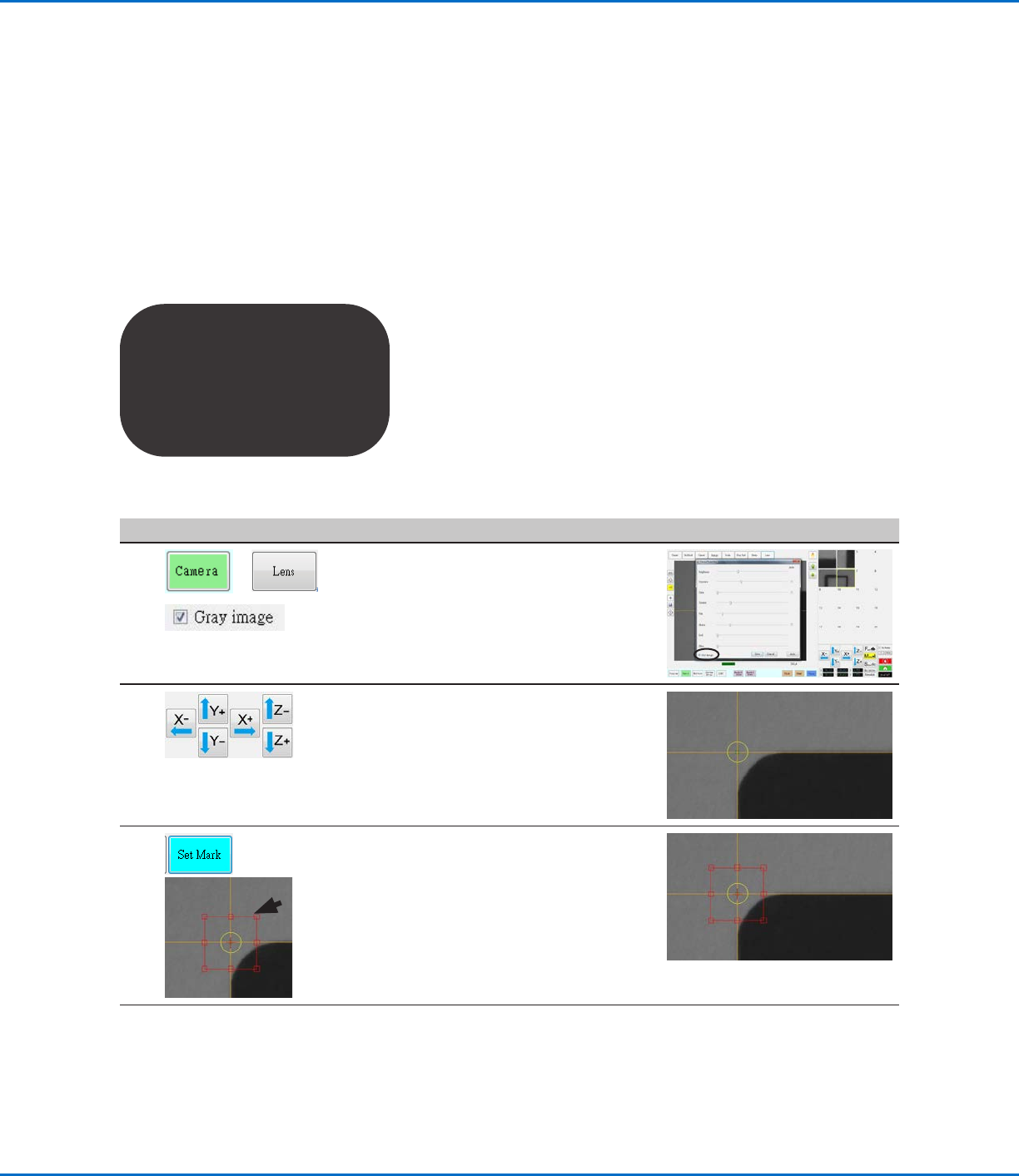
• Click CAMERA > LENS.
• Select the GRAY IMAGE checkbox.
NOTE: Selecting Gray image is
optional, but doing so provides
a sharper image and also slightly
zooms out the image.
2 • Jog the camera to the top left
corner of the workpiece template,
positioning the crosshairs along the
top and left sides of the template.
3
>
• Click SET MARK, then drag to
position the red box at the top left
corner of the workpiece template.
NOTE: If needed, refer to the robot
operating manual for a detailed
procedure on how to create a mark.
Continued on next page
Using the Arrow Types (continued)
OptiSure Automated Optical Inspection
38 www.nordsonefd.com info@nordsonefd.com +1-401-431-7000 Sales and service of Nordson EFD dispensing systems are available worldwide.
# Click Step Reference Image
4
>
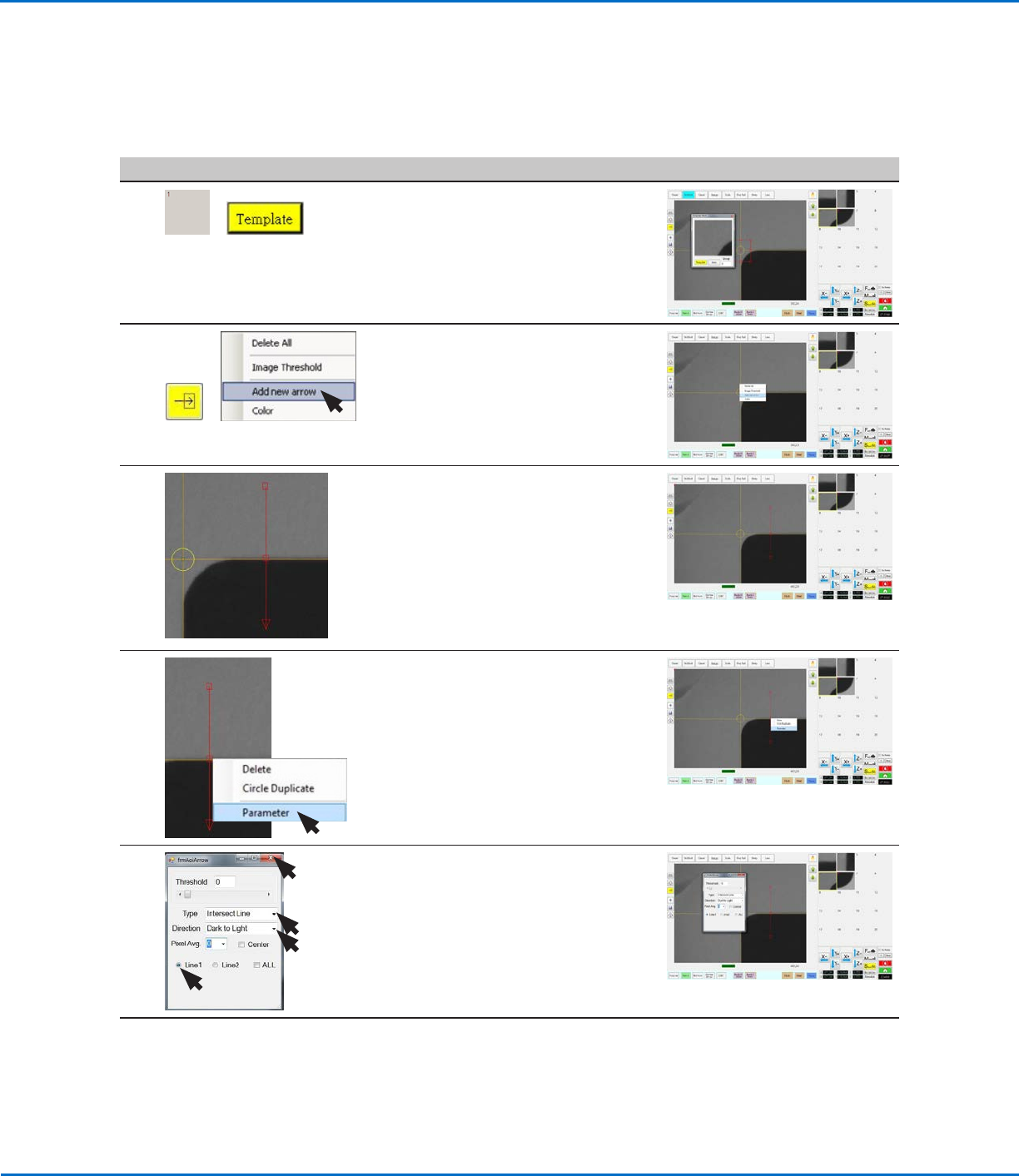
• Click a socket in the Mark Library to
save the mark, then click TEMPLATE
when the Template Match window
appears.
The system saves the image in the
Mark Library.
5
>
• Click the ARROW icon.
• In the Primary View screen, right-
click and select ADD NEW ARROW.
The system adds an arrow (called
Arrow A in this example) to the
screen.
6
1.
2.
3.
A
• Use the mouse to manipulate the
arrow so that it extends from the
outside of the rectangle to the
inside, as shown.
- To move the entire arrow, click
and drag the middle box (item 1).
- To elongate or shorten the arrow,
click and drag the arrow point
(item2) or the upper box (item 3).
7
4.
A
• Right-click the middle box (item4)
of the arrow and then select
PARAMETER.
The AOI Arrow window opens.
8 • Select the following for Arrow A:
- Type: INTERSECT LINE.
- Directon: DARK TO LIGHT.
- LINE1.
• Close the dialog box to save the
settings.
Continued on next page
Intersect Line Example (continued)
To Create an Intersect Line Mark Image (continued)
Using the Arrow Types (continued)