Nordson_EFD_OptiSure_Operating_Manual - 第40页
OptiSure Automated Optical Inspection 40 www.nordsonefd.com info@nordsonefd.com +1-401-431-7000 Sales and service of Nordson EFD dispensing systems are available worldwide. # Click Step Reference Image 14 • Select the fo…
OptiSure Automated Optical Inspection
39www.nordsonefd.com info@nordsonefd.com +1-401-431-7000 Sales and service of Nordson EFD dispensing systems are available worldwide.
# Click Step Reference Image
9
5.
SHIFT +
A B
• Create Arrow B by copying Arrow A.
NOTE: To copy an arrow, press and
hold the SHIFT key, click and hold
the middle box (item5), and then
drag to duplicate the arrow. The
copied arrow will have the same
Parameter settings.
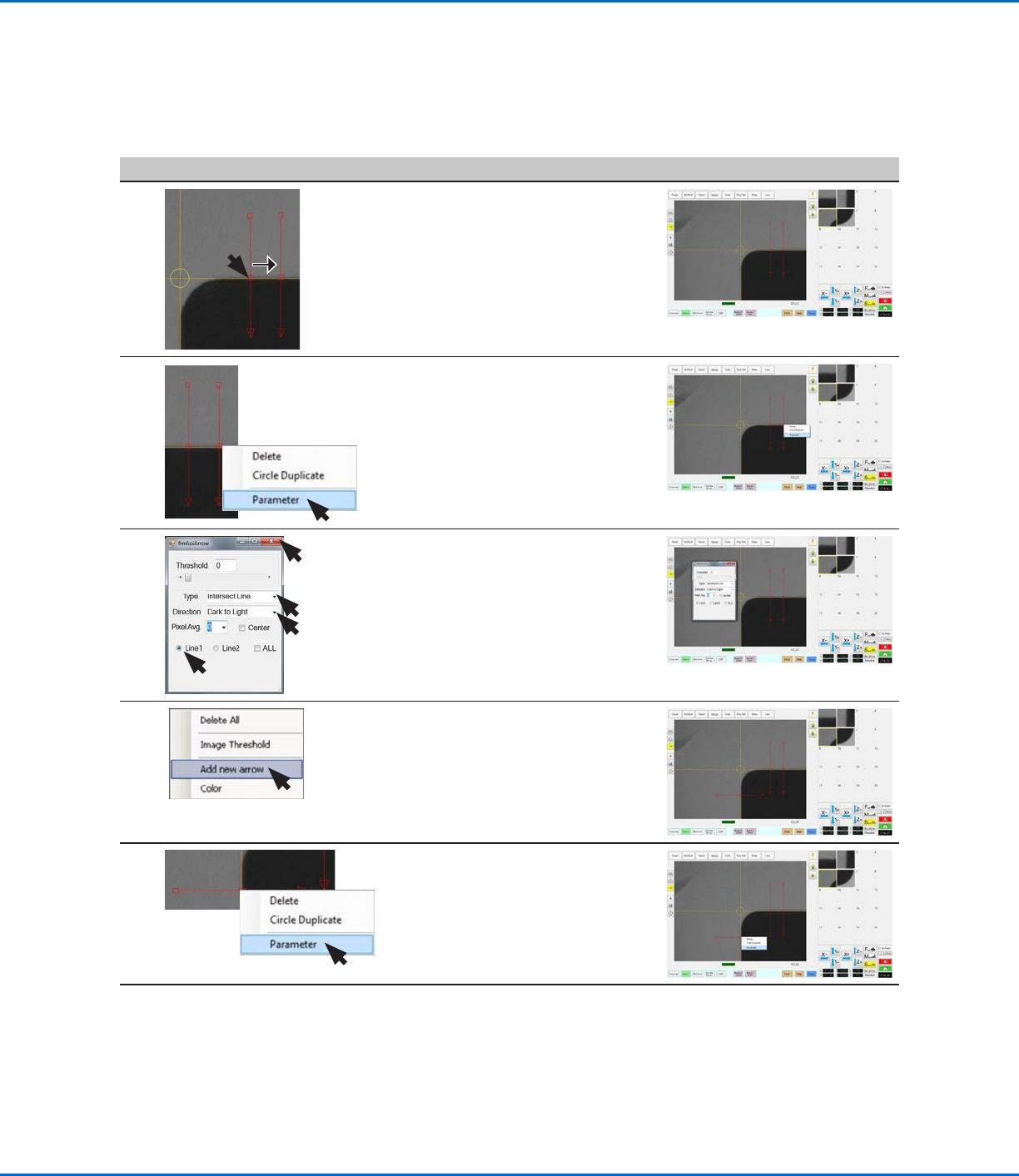
10 A B
6.
• Right-click the middle box (item6)
of the new Arrow B and then select
PARAMETER.
11 • Verify the following for Arrow B:
- Type: INTERSECT LINE.
- Directon: DARK TO LIGHT.
- LINE1.
• Close the dialog box.
12
• In the Primary View screen, right-
click and select ADD NEW ARROW
to create Arrow C on the vertical
edge of the workpiece.
13
C
• Right-click the middle box of the
new Arrow C and then select
PARAMETER.
Continued on next page
Using the Arrow Types (continued)
Intersect Line Example (continued)
To Create an Intersect Line Mark Image (continued)
OptiSure Automated Optical Inspection
40 www.nordsonefd.com info@nordsonefd.com +1-401-431-7000 Sales and service of Nordson EFD dispensing systems are available worldwide.
# Click Step Reference Image
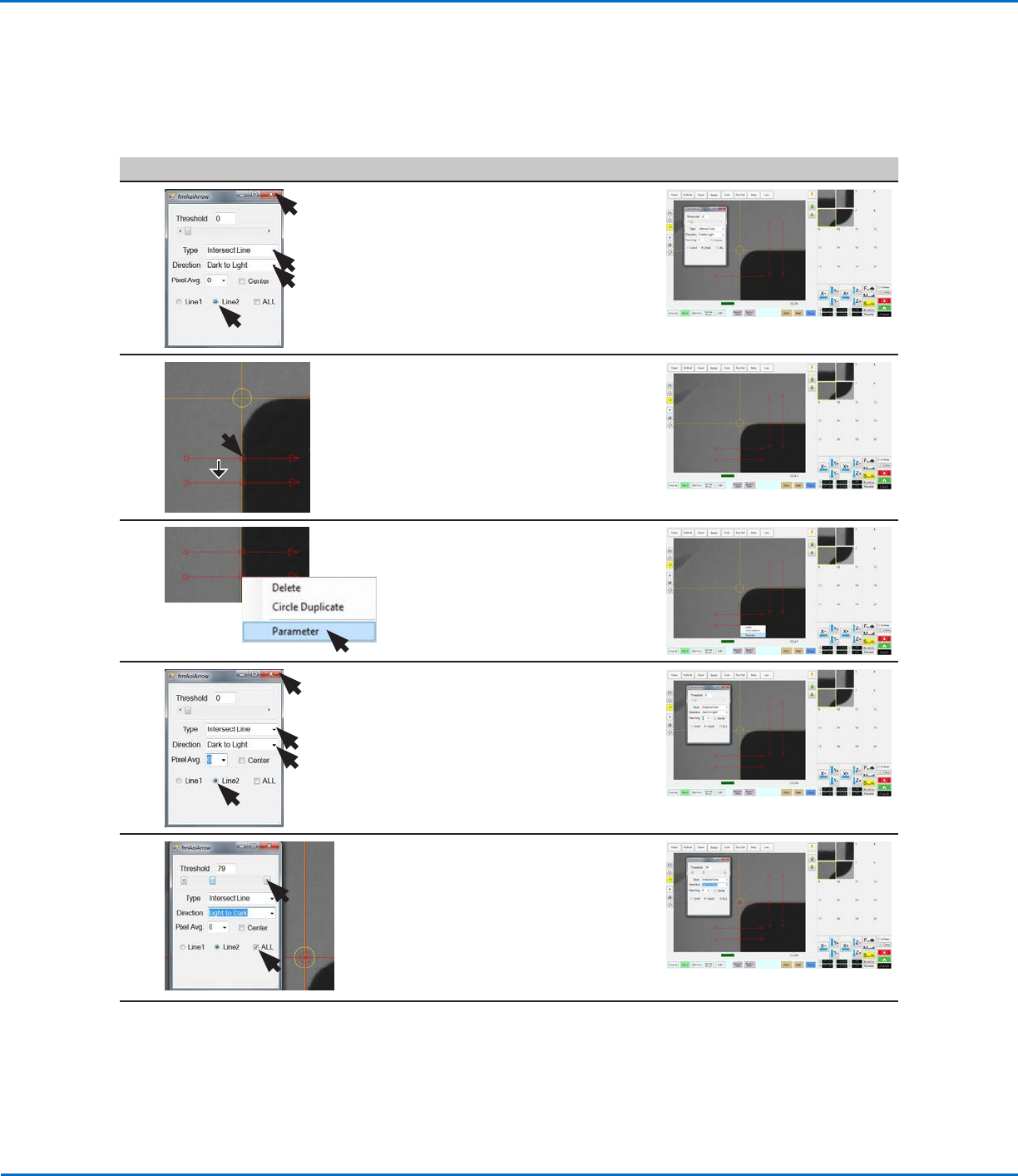
14
• Select the following for Arrow C:
- Type: INTERSECT LINE.
- Directon: DARK TO LIGHT.
- LINE2.
• Close the dialog box to save the
settings.
15
7.
SHIFT +
C
D
• Copy Arrow C and drag the copy
down to create Arrow D.
16
C
D
8.
• Right-click the middle box (item8)
of the new Arrow D and then select
PARAMETER.
17 • Verify the following for Arrow D:
- Type: INTERSECT LINE.
- Directon: DARK TO LIGHT.
- LINE2.
NOTE: Do not close this dialog
box. The next steps will make
adjustments to all the arrows.
18
9.
• Select the ALL checkbox (to cause
the system to enter the same
settings for all arrows).
• Change Direction to LIGHT TO
DARK.
• Adjust THRESHOLD until the
crosshairs (item 9) appear on the
camera screen.
Continued on next page
Using the Arrow Types (continued)
Intersect Line Example (continued)
To Create an Intersect Line Mark Image (continued)
OptiSure Automated Optical Inspection
41www.nordsonefd.com info@nordsonefd.com +1-401-431-7000 Sales and service of Nordson EFD dispensing systems are available worldwide.
Intersect Line Example (continued)
To Create an Intersect Line Mark Image (continued)
Using the Arrow Types (continued)
# Click Step Reference Image
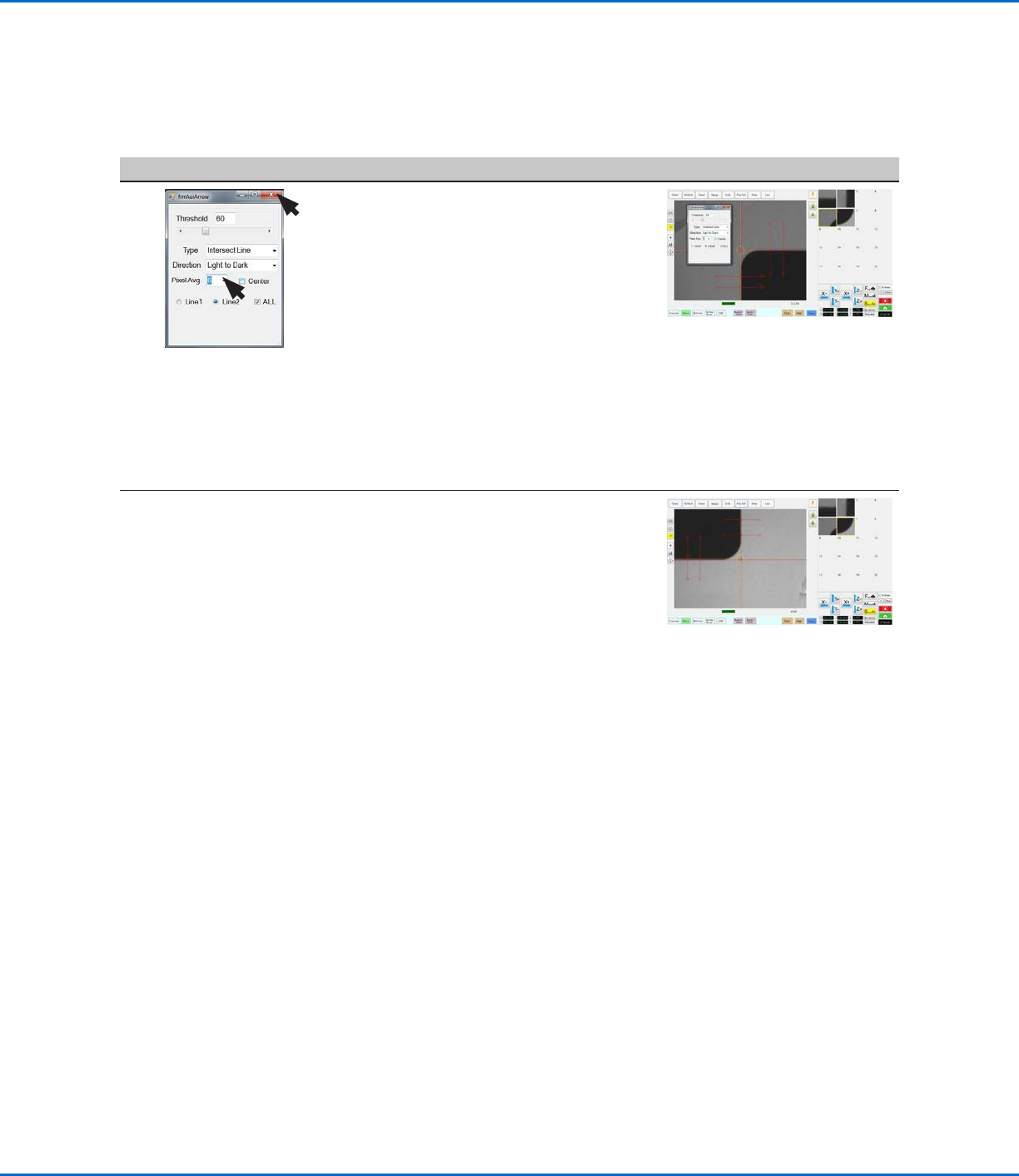
19
• Adjust PIXEL AVG to make the mark
image easier for the system to find.
• Close the dialog box to save the
settings.
The first mark image (No. 5 in this
example) is now complete.
• If you have not already done so,
start creating your program and
add a Fiducial Mark command that
references this mark image (No.5 in
this example).
NOTE: Refer to “To Use Intersect
Line Mark Images in a Program” on
page42 for the complete example
program.
20 • Repeat the applicable steps in this
procedure to create a mark image
and set of arrows for the bottom
right corner of the workpiece
template.
This set of arrows will be the second
mark image (No. 6 in this example).
• In your program, add a second
Fiducial Mark command that
references this mark image (No.6 in
this example).
NOTE: Refer to “To Use Intersect
Line Mark Images in a Program” on
page42 for the complete example
program.