Nordson_EFD_OptiSure_Operating_Manual - 第43页
OptiSure Automated Optical Inspection 43 www.nordsonefd.com info@nordsonefd.com +1-401-431-7000 Sales and service of Nordson EFD dispensing systems are available worldwide. Mea. Point T o Line Example Mea. Point to Line …
OptiSure Automated Optical Inspection
42 www.nordsonefd.com info@nordsonefd.com +1-401-431-7000 Sales and service of Nordson EFD dispensing systems are available worldwide.
To Use Intersect Line Mark Images in a Program
# Click Step Reference Image
1
• In the dispense program, ensure
that Fiducial Mark commands are
inserted as noted in the previous
procedure: One for the top left
corner mark image and one for the
bottom right corner mark image that
you created. The complete example
program is provided below.
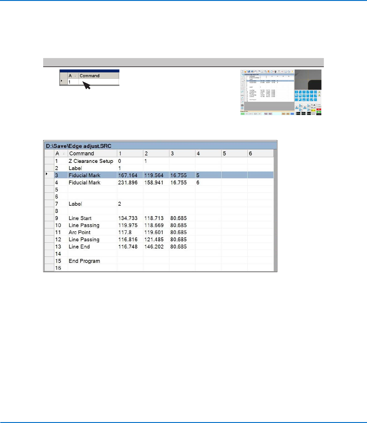
Example program that contains Fiducial Mark commands (lines 3–4) for Intersect Line marks
Using the Arrow Types (continued)
Intersect Line Example (continued)
OptiSure Automated Optical Inspection
43www.nordsonefd.com info@nordsonefd.com +1-401-431-7000 Sales and service of Nordson EFD dispensing systems are available worldwide.
Mea. Point To Line Example
Mea. Point to Line is an OptiSureAOI feature used in tandem with the Arrow Check Point command. This feature
measures the width between two specified points on a dispensed line, compares the measurement to a set of points
on a subsequent dispense, and then, depending on the user-specified parameters, determines if the dispense is
acceptable. If the dispense does not meet the specified criteria, the system takes the action specified in the Arrow
Check Point command.
PREREQUISITES
To learn how to use this feature, draw a line on a sheet of white paper and use it as a workpiece template.
To Create a Mark Image for the Desired Line Width
# Click Step Reference Image
1
>
>
1.
2.
>
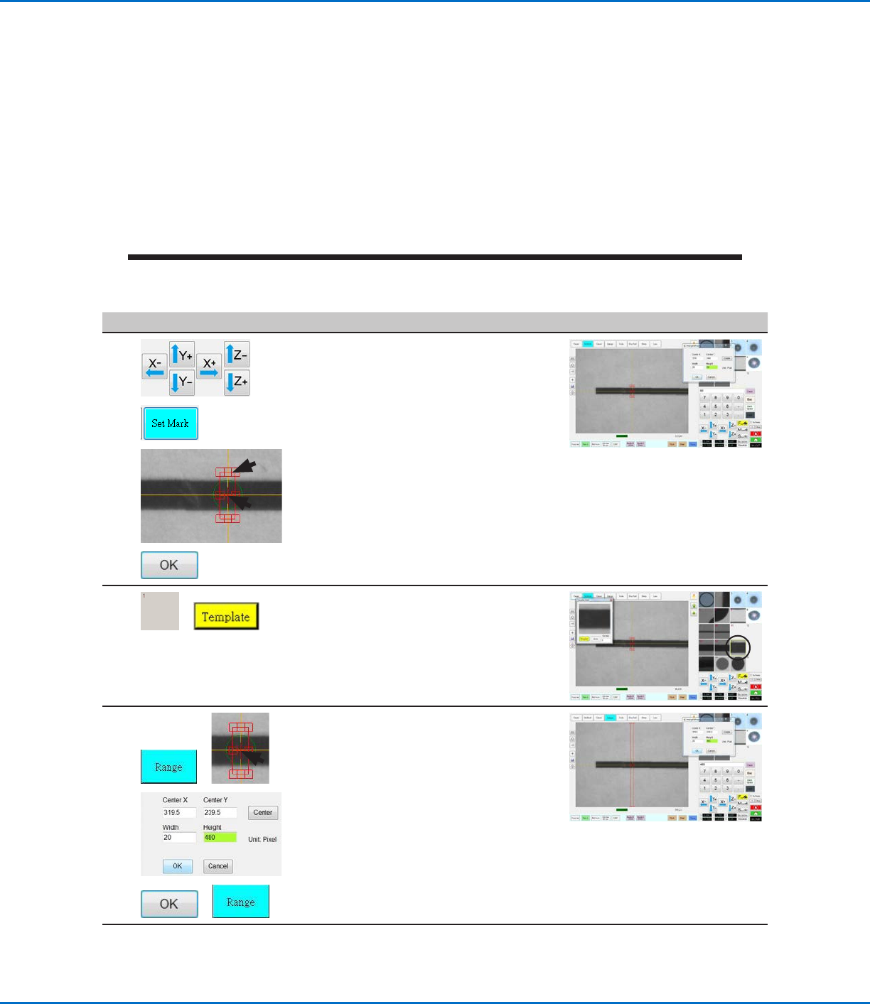
• Jog the camera to a location on the
line.
• Click SET MARK, then drag to position
the red box (item 1) over the line.
• Double-click the crosshairs in the
center of the red box (item 2) and then
enter the desired values for Width and
Height (20 and 60 in this example).
• Click OK to save the values.
2
>
• Click a socket in the Mark Library to
save the mark, then click TEMPLATE
when the Template Match window
appears.
The system saves the image in the
Mark Library.
3
>
>
>
• Click RANGE to set where the system
searches for the mark.
• Double-click on the crosshairs in the
center of the mark and enter Width
and Height values (20 and 480 in this
example).
NOTE: The Width value must be the
same as the Width specified in step 1
above.
• Click OK.
• Click RANGE again to save.
Continued on next page
Using the Arrow Types (continued)
OptiSure Automated Optical Inspection
44 www.nordsonefd.com info@nordsonefd.com +1-401-431-7000 Sales and service of Nordson EFD dispensing systems are available worldwide.
Using the Arrow Types (continued)
# Click Step Reference Image
4
>
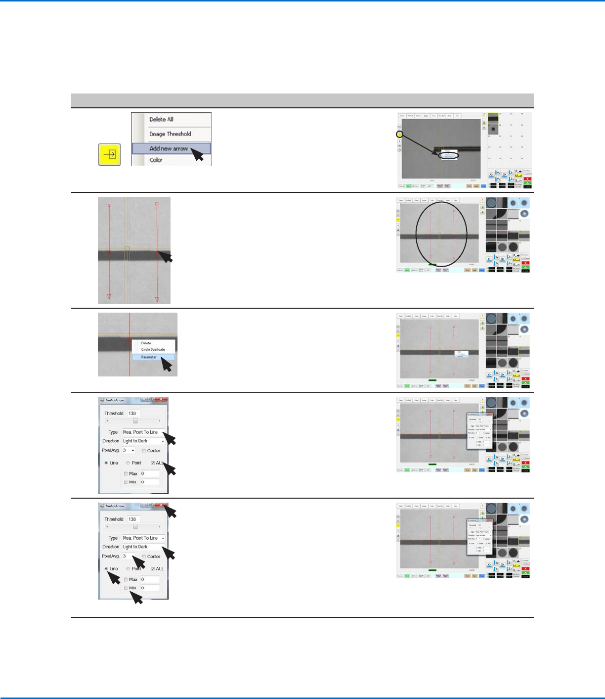
• Click the ARROW icon.
• In the Primary View screen, right-click
and select ADD NEW ARROW.
The system adds an arrow to the
screen.
5
3.
4.
5.
• Repeat step 4 to add another arrow,
and then use the mouse to manipulate
the arrows so they form an array, as
shown.
- To move the entire arrow, click and
drag the middle box (item4).
- To elongate or shorten the arrow,
click and drag the arrow (item5) or
the end box (item 3).
6 • Right-click on the middle box of an
arrow and then select PARAMETER.
The AOI Arrow window opens.
7 • Select the ALL checkbox.
• For Type, select MEA. POINT TO LINE.
8 • Select LIGHT TO DARK.
• Adjust PIXEL AVG to make the mark
image easier for the system to find.
• Check CENTER if you want to center
the image based on the image in the
mark library.
• Select the LINE radio button.
• Deselect the MAX and MIN
checkboxes.
Continued on next page
Mea. Point To Line Example (continued)
To Create a Mark Image for the Desired Line Width (continued)