Nordson_EFD_OptiSure_Operating_Manual - 第46页
OptiSure Automated Optical Inspection 46 www.nordsonefd.com info@nordsonefd.com +1-401-431-7000 Sales and service of Nordson EFD dispensing systems are available worldwide. # Click Step Reference Image 13 • Select LIGHT …
OptiSure Automated Optical Inspection
45www.nordsonefd.com info@nordsonefd.com +1-401-431-7000 Sales and service of Nordson EFD dispensing systems are available worldwide.
# Click Step Reference Image
9
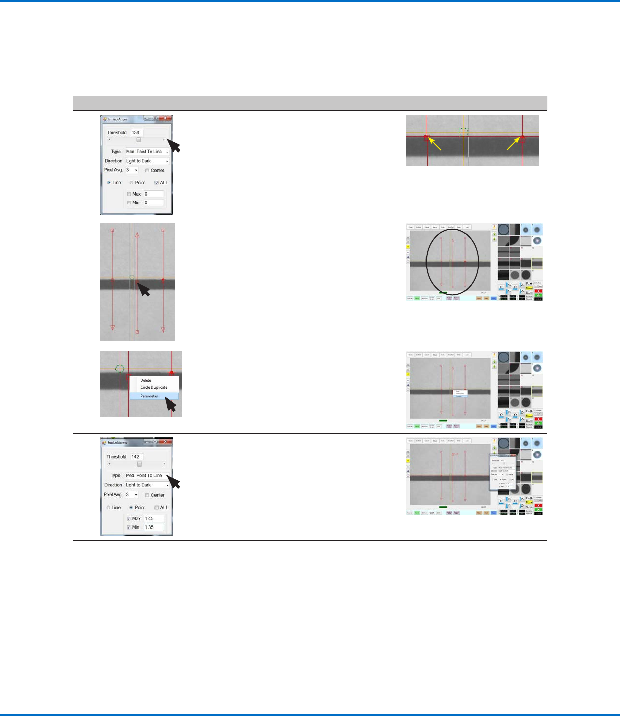
• Adjust THRESHOLD until the two small
red circles (item 6) are positioned on
the top edge of the line.
• Close the dialog box to save the
settings.
6.
6.
10
A.
C.
B.
• Repeat step 4 to add another arrow,
and then use the mouse to manipulate
the new arrow C such that it is in the
middle between arrows A and B, as
shown.
NOTE: This function will still work
properly if arrow C is not exactly in the
middle.
11 • Right-click on the middle box of an
arrow C and then select PARAMETER.
The AOI Arrow window for Arrow C
opens.
12 • For Type, select MEA. POINT TO LINE.
Continued on next page
Mea. Point To Line Example (continued)
To Create a Mark Image for the Desired Line Width (continued)
Using the Arrow Types (continued)
OptiSure Automated Optical Inspection
46 www.nordsonefd.com info@nordsonefd.com +1-401-431-7000 Sales and service of Nordson EFD dispensing systems are available worldwide.
# Click Step Reference Image
13
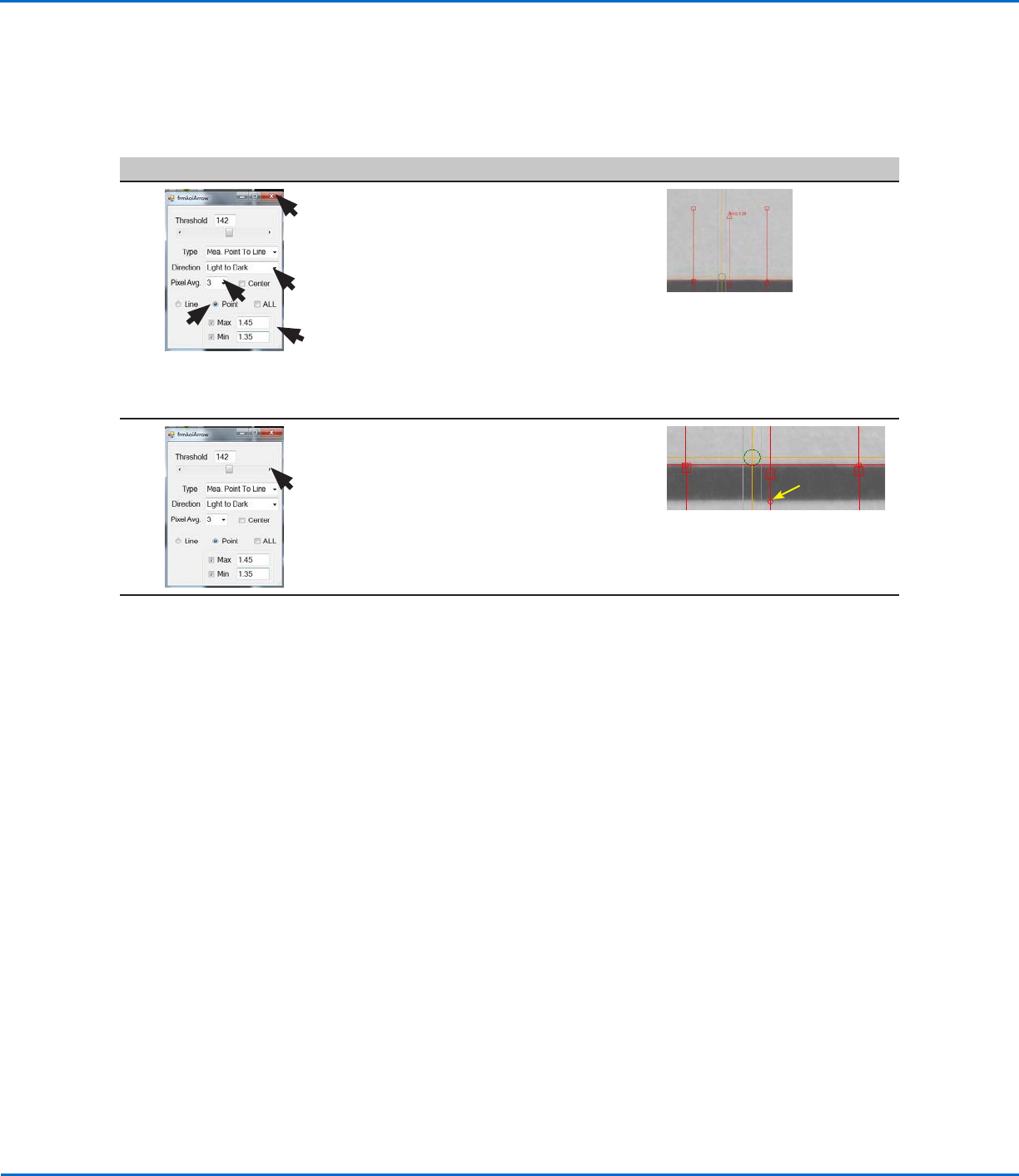
• Select LIGHT TO DARK.
• Adjust PIXEL AVG to make the mark
image easier for the system to find.
• Select the POINT radio button.
• For MAX, select the checkbox and
enter the maximum allowable width of
the line. The displayed AVG (average)
value is equal to the line width.
• For MIN, select the checkbox and
enter the minimum allowable width of
the line.
14 • Adjust THRESHOLD until the small red
circle of the middle arrow (item 7) is
positioned on the bottom edge of the
line.
• Close the dialog box to save the
settings.
7.
The saved mark image is now ready to be specified in an Arrow Check
Point command to cause the system to check the width of a dispensed line
anywhere on the line. In this example, the checked width must be within
1.35–1.45 mm (as defined in step 13). If the width is greater or lower, a
warning box appears.
Continue to “To Use Arrow Check Point in a Program (Mea. Point to Line
Example)” on page47 to use the mark image.
NOTE: The system can return to the middle of a dispensed line only if the
middle of the line is within the range specified in step 3 on page43.
Using the Arrow Types (continued)
Mea. Point To Line Example (continued)
To Create a Mark Image for the Desired Line Width (continued)
OptiSure Automated Optical Inspection
47www.nordsonefd.com info@nordsonefd.com +1-401-431-7000 Sales and service of Nordson EFD dispensing systems are available worldwide.
To Use Arrow Check Point in a Program (Mea. Point to Line Example)
# Click Step Reference Image
1
> ARROW CHECK
POINT >
>
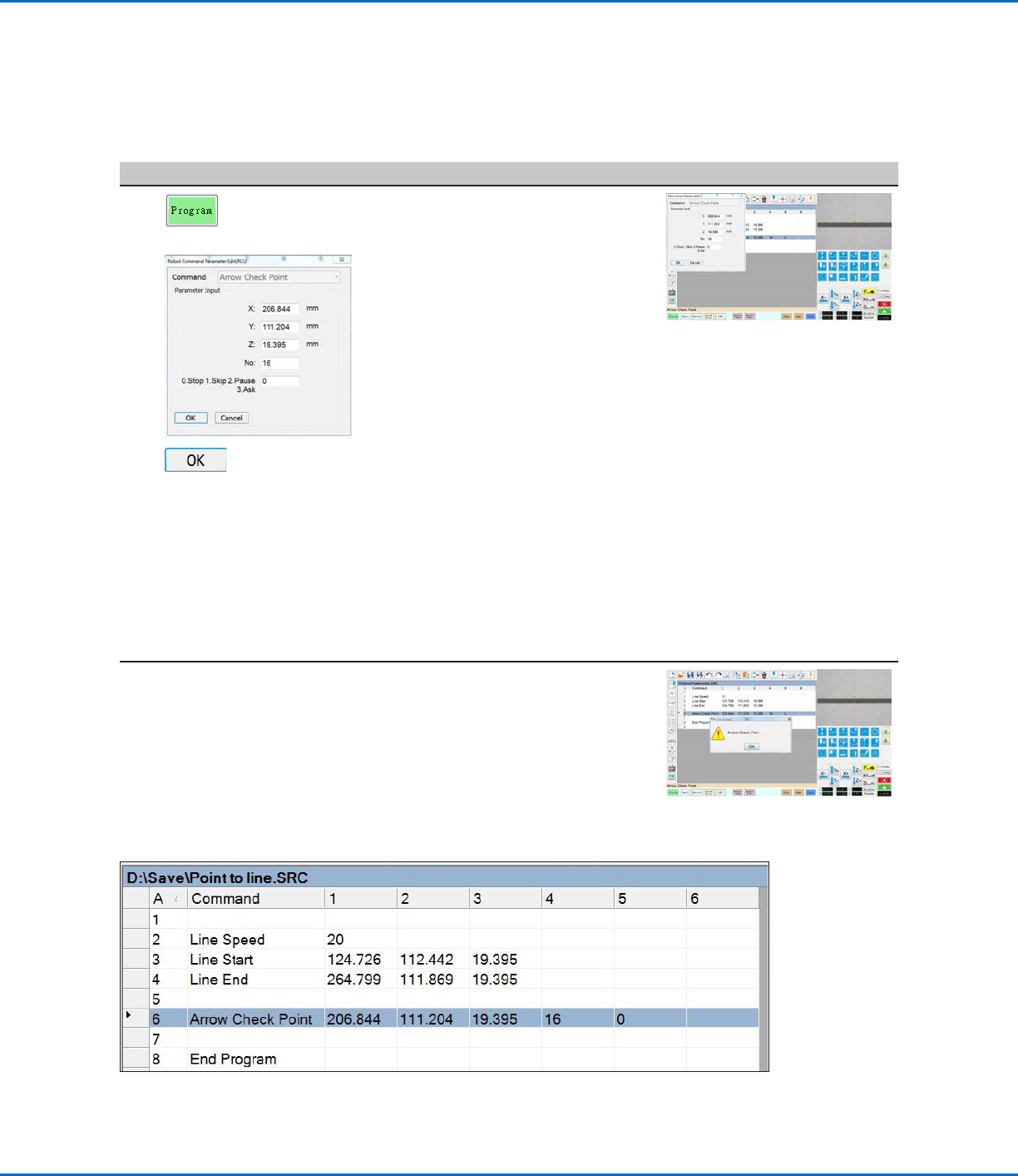
• Click the PROGRAM tab.
• Insert commands to dispense a
line over the line on the workpiece
template.
NOTE: The complete example
program is provided below.
• Jog the camera to a location on the
line where you want the system to
check the width of a section.
• Insert an ARROW CHECK POINT
command and enter parameters as
follows:
- Enter the number (No.) of the mark
image created for the line in the
previous procedure.
- Select the action you want the
system to take if the measured line
section is above the Max value
or below the Min value specified
for the mark image (step 13 on
page46). Refer to “Arrow Check
Point” on page71 for details.
• Click OK.
When the system executes the Arrow Check Point command and
finds an unacceptable line section, it takes the action specified by the
Stop, Skip, Pause, Ask parameter. Refer to “Arrow Check Point” on
page71 for details.
Mea. Point To Line Example (continued)
Using the Arrow Types (continued)
Example program that contains an Arrow Check Point command for verifying line width