Nordson_EFD_OptiSure_Operating_Manual - 第57页
OptiSure Automated Optical Inspection 57 www.nordsonefd.com info@nordsonefd.com +1-401-431-7000 Sales and service of Nordson EFD dispensing systems are available worldwide. Mea. Width Example for Dispense Width Adjustmen…
OptiSure Automated Optical Inspection
56 www.nordsonefd.com info@nordsonefd.com +1-401-431-7000 Sales and service of Nordson EFD dispensing systems are available worldwide.
Using the Arrow Types (continued)
# Click Step Reference Image
3
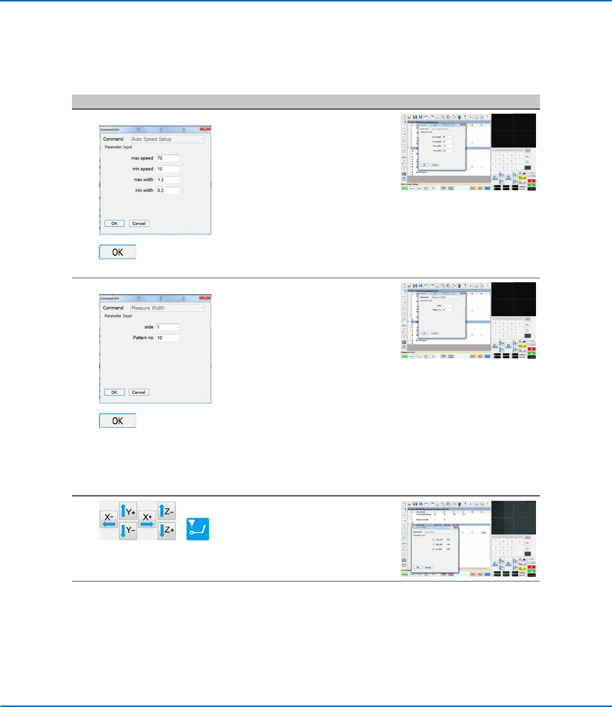
AUTO SPEED SETUP >
>
• Under the Arrow Check Point
command, insert an AUTO SPEED
SETUP command and enter
parameters as follows:
- Max. Speed: Enter the maximum
allowable robot line speed.
- Min. Speed: Enter the minimum
allowable robot line speed.
- Max. Width: Enter the maximum
allowable width of the line.
- Min. Width: Enter the minimum
allowable width of the line.
• Click OK.
4
MEASURE WIDTH >
>
• Under the Auto Speed Setup
command, insert a MEASURE WIDTH
command and enter parameters as
follows:
- Side: Enter a SIDE number to
specify the line to be measured
(refer to “Auto Speed” on
page72 for a diagram that
explains this parameter).
- Pattern No: Enter the number of the
mark image created for the line in
the previous procedure (No. 10 in
this example).
• Click OK.
NOTE: This command measures the
width of the dispensed line using the
coordinates specified in the Arrow
Check Point command.
5
>
• Jog the camera to the beginning of
the thinner line.
• In the next empty command address,
enter a LINE START command.
Continued on next page
Mea. Width Example for Dispense Width Adjustment (continued)
To Create a Program for Dispense Width Adjustment (continued)
OptiSure Automated Optical Inspection
57www.nordsonefd.com info@nordsonefd.com +1-401-431-7000 Sales and service of Nordson EFD dispensing systems are available worldwide.
Mea. Width Example for Dispense Width Adjustment (continued)
To Create a Program for Dispense Width Adjustment (continued)
Using the Arrow Types (continued)
# Click Step Reference Image
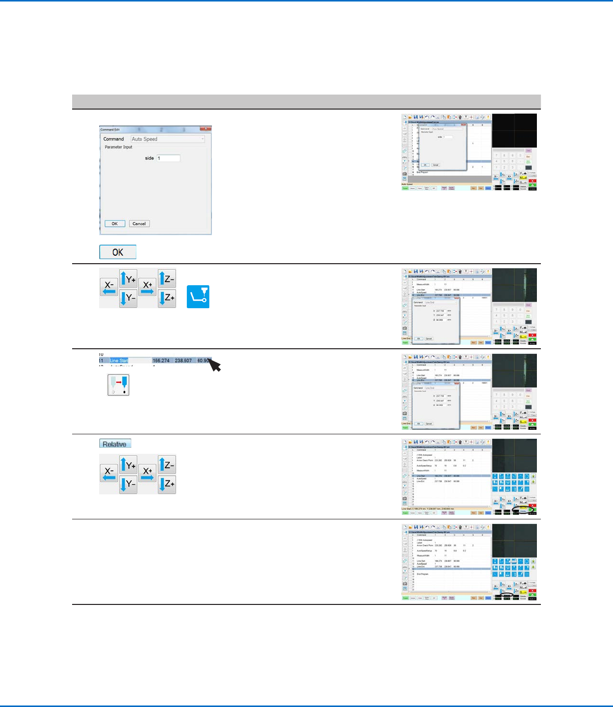
6
AUTO SPEED >
>
• Insert an AUTO SPEED command.
• For Side, enter the SIDE number
specified previously (in step 4, which
is Side 1 in this example).
• Click OK.
7
>
• Jog the camera to the end of the
thinner line.
• In the next empty command address,
enter a LINE END command.
8
>
• Highlight (select) the Line Start
command.
• Click Move to return the camera to
the beginning of the thinner line.
9
>
• Click RELATIVE.
• Jog the camera to the thicker line on
the workpiece template.
10 • Stop when you reach the new line,
then make a note of the relative Y
offset (13.087 in this example).
Continued on next page
OptiSure Automated Optical Inspection
58 www.nordsonefd.com info@nordsonefd.com +1-401-431-7000 Sales and service of Nordson EFD dispensing systems are available worldwide.
Using the Arrow Types (continued)
Mea. Width Example for Dispense Width Adjustment (continued)
To Create a Program for Dispense Width Adjustment (continued)
# Click Step Reference Image
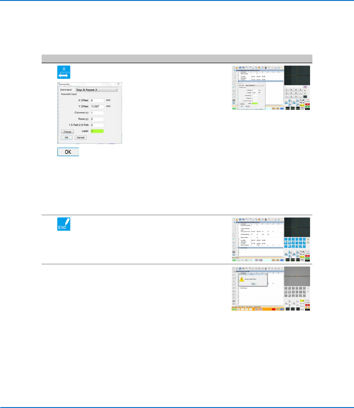
11
>
>
• Under the Line End command, insert
a STEP & REPEAT X command and
enter parameters as follows:
- X Offset: Enter 0.
- Y Offset: Enter the relative Y
offset determined in step 10 on
page57 (13.087 in this example).
- Columns (x): Enter 1.
- Rows (y): Enter 2.
NOTE: In this example, there is one
column and two rows of lines.
- 1.S Path 2.N Path: Enter 2 so that
dispensing starts at the beginning
of the line.
- Label: Enter 1 so the program
returns to the top and repeats.
NOTE: The Change button toggles
this parameter between Label and
Address.
• Click OK.
12 • Insert an END PROGRAM command
to complete the program.
When the system executes the Arrow
Check Point command and finds an
unacceptable line section, it takes the
action specified by the Stop, Skip,
Pause, Ask parameter. Refer to “Arrow
Check Point” on page71 for details.
Once the line width is verified, the
system continues running the program,
automatically adjusting the dispenser
speed as needed to produce the correct
line width.
NOTE: The complete example program
is provided on the next page.