00197902-03_UM_X-Serie-S_EN.pdf - 第129页
User manual SIPLACE X-Series 3 Technical data and assemblies From software version 710.0 Edition 12/2016 3.4 Overview of the modules 129 3.4 Overview of the modules 3 3 Fig. 3.4 - 1 Overview of assemblies - example of X3…
3 Technical data and assemblies User manual SIPLACE X-Series
3.3 Dimensions and weight From software version 710.0 Edition 12/2016
128
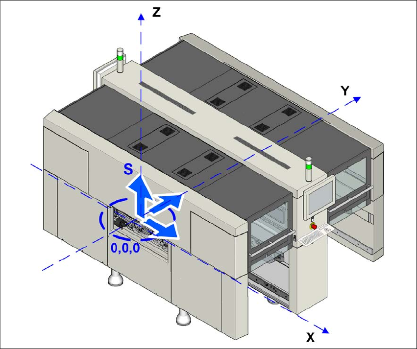
3.3.3 Center of gravity
3
Fig. 3.3 - 4 Center of gravity in millimeters (example of SIPLACE X2 S / X3 S / X4 S shown)
X coordinate 0 mm
Y coordinate 0 mm
Z coordinate 630 mm
These center of gravity coordinates relate to placement machines with a PCB conveyor height of
900 mm.
User manual SIPLACE X-Series 3 Technical data and assemblies
From software version 710.0 Edition 12/2016 3.4 Overview of the modules
129
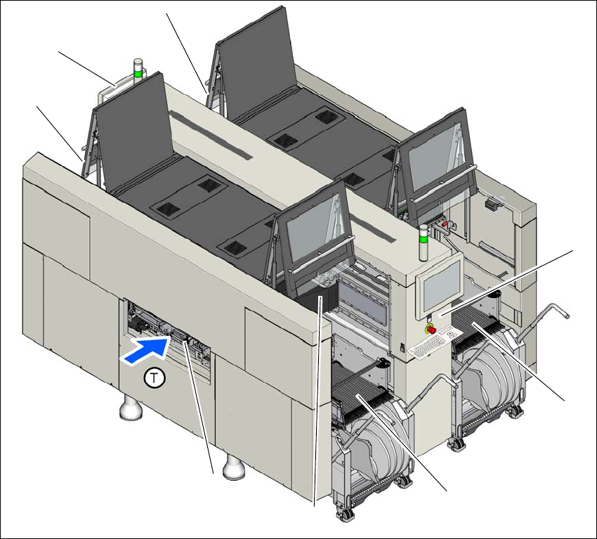
3.4 Overview of the modules
3
3
Fig. 3.4 - 1 Overview of assemblies - example of X3 S shown
(1) Location 1 with component trolley, tape cutter, empty tape duct
(2) Location 2 with component trolley, tape cutter, empty tape duct
(3) Location 3 with COT insert, tape cutter, empty tape duct
(4) Location 4 with COT insert, tape cutter, empty tape duct
(5) Gantry 1 at location 1 with placement head
(6) Monitor with keyboard (2x)
(7) Board conveyor
(T) Direction of PCB transport
(1)
(2)
(3)
(4)
(6)
(7)
(7)
(5)
3 Technical data and assemblies User manual SIPLACE X-Series
3.5 Placement head From software version 710.0 Edition 12/2016
130
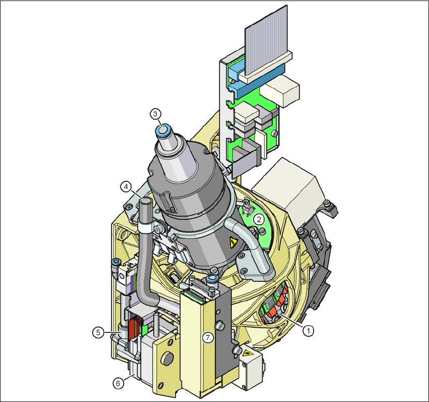
3.5 Placement head
3.5.1 SIPLACE SpeedStar C&P20 for high speed placement
3
Fig. 3.5 - 1 SIPLACE SpeedStar - function group part 1
(1) DP drive, 20 drives
(2) "Vacuum sensor hold circuit" board
(3) Compressed air connection for 20 Venturi nozzles in the pickup/placement and holding circuit
(4) Line for the exhaust air from the pressure control valve (7)
(5) Return cylinder
(6) Z motor (linear motor)
(7) Pressure control valve