00197902-03_UM_X-Serie-S_EN.pdf - 第218页
4 Setting up and commissioning User manual SIPLACE X-Series 4.2 Infrastructure at the installation location From software versio n 710.0 Edition 12/2016 218 4.2.3.3 Power supply cable - specificati on The following speci…
User manual SIPLACE X-Series 4 Setting up and commissioning
From software version 710.0 Edition 12/2016 4.2 Infrastructure at the installation location
217
4.2.3.1 Danger notes
4
4
4.2.3.2 Checking the main power supply
Check whether the power supply complies with the prescribed machine specifications (see table
in section 3.2.3
, page 121).
4
DANGER
Dangerous voltage levels!
The machine is supplied with 3 x 360 V~ to 3 x 480 V ± 10 %, 50/60 Hz or optionally with
3 x 200 V~ to 3 x 240 V~ ± 10 %; 50/60 Hz mains voltage. This means that some parts of
the system carry potentially lethal voltages - even when switched off at the main power
switch and with disconnected mains plug.
Incorrect handling of this machine can therefore result in death or severe injury or consid-
erable damage to equipment.
Always follow the applicable accident prevention and DIN regulations (particularly EN
60204, part 1 or IEC 60204, part 1) and the applicable regulations in your own coun-
try.
The covers over the power supply unit may ONLY be opened by appropriately quali-
fied and trained personnel.
DANGER
Lethal voltages under the safety cutoff (CSB) cover!
Under the cover there are components which could still carry lethal voltages, even when
the machine is switched off and the mains plug has been disconnected. After disconnect-
ing the mains plug, wait 5 minutes until the capacitors have discharged.
Never open the covers.
Only ASM Assembly Systems GmbH&Co.KG service engineers or the machine
owner's service engineers, who have been trained by ASM, may perform work on the
power supply and the safety cutoff (CBS).
PLEASE NOTE
Load peaks in power supply
For technical reasons, load peaks occur in the power supply.
Please contact your power company to clarify the mains impedance, if necessary.
4 Setting up and commissioning User manual SIPLACE X-Series
4.2 Infrastructure at the installation location From software version 710.0 Edition 12/2016
218
4.2.3.3 Power supply cable - specification
The following specifications apply to the power supply cable for the machine:
– 5 x 4 mm² at 3 x 360 V~ to 3 x 480 V ± 10 %, 50/60 Hz mains voltage
– 5 x 4 mm² for 3 x 200 V~ to 3 x 240 V~ ± 10 %; 50/60 Hz mains voltage.
The color coding for the wires will depend on the country in which the system is operated.
4
4
WARNING
Cross-section and length of mains connection cable
The cross-section and length of the mains connection cable influence the Short-Circuit-
Current-Rating (SCCR) of the machine.
When replacing the mains connection cable, do not increase the cross-section of the
wires or shorten the length of the cable.
WARNING
Clear marking of electrical leads!
The electrical leads to each individual machine and to the options installed must be clear-
ly labeled and easily assignable.
The regulations of the country in which the machine is operated apply.
User manual SIPLACE X-Series 4 Setting up and commissioning
From software version 710.0 Edition 12/2016 4.2 Infrastructure at the installation location
219
4.2.3.4 Mains connection - delivery configuration
The main power connection is configured according to the power supply of the country concerned.
– The machine is configured for voltages of 3 x 200 V~ to 3 x 240 V~ ± 10 %; 50/60 Hz.
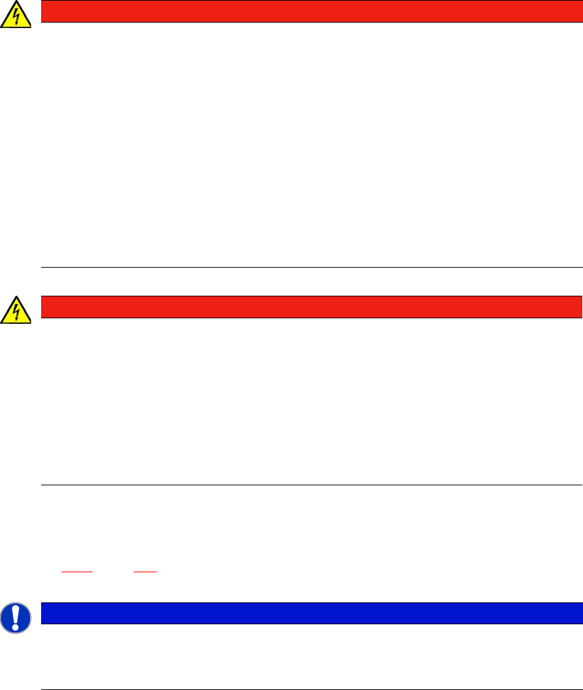
The machine has a mains power cable WITHOUT plug. 4
4
Fig. 4.2 - 4 Description of wires in the mains power cable
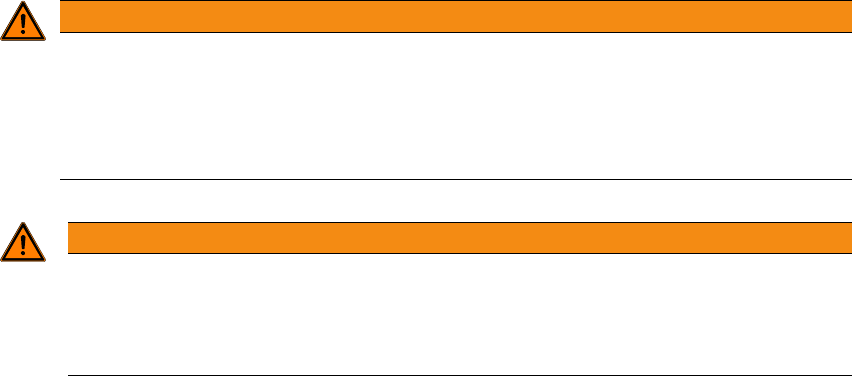
– The machine is configured for voltages of 3 x 360 V~ to 3 x 480 V ± 10 %, 50/60 Hz.
The machine has a mains power cable WITH Cekon plug. 4
4
Fig. 4.2 - 5 Assignment in the Cekon plug
1 = (L1): three-phase
2 = (L2): three-phase
3 = (L3): three-phase
4 = (N): neutral conductor
green/yellow = (PE): conductor
PE
L1
L2
L3
N